
Related Manuals for Enovation Controls MURPHY PowerView PV380-R2


Summary of Contents for Enovation Controls MURPHY PowerView PV380-R2
- Page 1 ® PowerView PV380-R2 Murphy Standard Configuration Operations Manual 2016-06-15 00-02-0997 Section 78...
- Page 2 Products covered in this document comply with European Council electromagnetic compatibility directive 2004/108/EC and electrical safety directive 2006/95/EC. In order to consistently bring you the highest quality, full-featured products, we reserve the right to change our specifications and designs at any time. The latest version of this manual can be found at www.fwmurphy.com.
-
Page 3: Table Of Contents
Table of Contents Introduction ............5 Engine and Transmission Parameters........6 Navigation and Keypad Functions .......... 6 First-Time Startup ......... 11 Parameter Gauge Settings ......15 Adjusting Menu Selections ......18 User Settings ............... 19 Service Reminders ............... 25 Regen .................. 26 Set Points ................ -
Page 4: Introduction
Introduction ® Congratulations on purchasing the PowerView Model PV380 R-2. This advanced tool provides monitoring of Tier 4/Euro Stage 4 compliant electronic engines. The PV380 monitors multiple J1939 parameters and provides basic engine alarm/shut-down information. This manual was developed to help you become familiar with the PV380 display, identify navigation basics and recognize useful options and features. -
Page 5: Engine And Transmission Parameters
Engine and Transmission Parameters The following are some of the engine and transmission parameters that can be displayed in standard units. • • Engine Speed Engine Fuel Level • • Engine Temperature Discharge Pressure • • Engine or Machine Hours of Suction Pressure •... - Page 6 When directed to press a symbol within the procedural steps, it is referring to the button below the displayed symbol. Each display button may have alternating functions within the configuration as shown in the tables below. Key 1 Function Alternates between parameter screen sets or moves the cursor one position to the left Moves highlight up when in certain Menu selections Decreases the number when in various screens...
- Page 7 Key 2 Function Displays Diagnostic Messages (Faults) and FAULTS Stored Codes Moves highlight down when in certain Menu selections Increases the number when various screens Key 3 Function Displays the Main Menu entrance point Serves as the Escape/Return to Previous Menu button 00-02-0997 2016-06-15...
- Page 8 Key 4 Function Decreases the Throttle set point Stored Displays the Stored Codes when in Diagnostic Codes Messages Decreases various settings Enters the OEM Menu Moves the cursor one slot at a time to the right 00-02-0997 2016-06-15...
- Page 9 Key 5 Function Increases the Throttle set point ACTIVE Displays the Active Faults screen FAULTS Serves as the Enter key for menu selections Increases various settings Moves the cursor to the next cell when customizing parameters on the home screen Moves the cursor one slot at a time to the right and displays alternate menu choices/screens 00-02-0997...
-
Page 10: First-Time Startup
First-Time Startup When power is applied to the PV380, the Warning and Shutdown lights illuminate and the Murphy logo displays. On electronic engines, if a preheat message is being actively broadcast from the Engine Control Unit (ECU), a Wait to Start symbol displays below the Murphy logo as shown in the next image. - Page 11 NOTE: The above screen will not be displayed for mechanical engines. The PV380 will skip the Wait to Start (WTS) screen if the ECU stops transmitting the WTS message or if the engine speed is >500 RPM. However, if the ECU never transmits the WTS message, the user will only see the splash screen for three seconds after the key is turned on then the gauge screen appears.
- Page 12 Once the engine is running (> 500 RPM), the engine information (electrical or mechanical) will display and alternate with the chosen parameter set when the key is pressed. Engine – Electrical Parameter Set – Electrical (default parameters) 00-02-0997 2016-06-15...
- Page 13 Engine – Mechanical Parameter Set – Mechanical (default parameters) 00-02-0997 2016-06-15...
-
Page 14: Parameter Gauge Settings
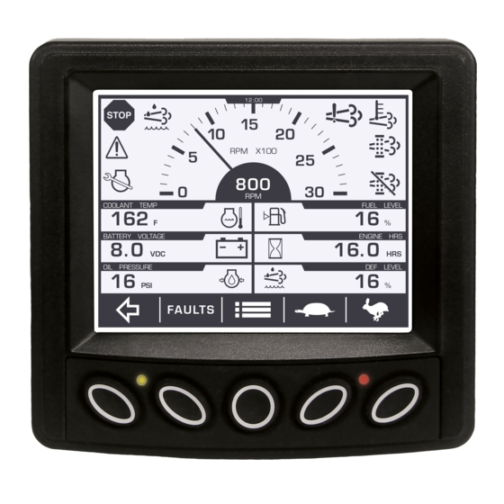
Parameter Gauge Settings 1. Alert and Warning Icon area: Up to eight symbols can be shown at one time in the icon area to represent warnings, Tier 4 status and service indicators. The most important symbol will be shown in the upper left. The following symbols can be shown in this area: 00-02-0997 2016-06-15... - Page 15 Icon(s) Function(s) Shutdown (electronic or by mechanical set point) Warning HEST Regen Inhibit (Regen Inhibit is restricted when a HEST alarm is present) Diesel Particulate Filter (DPF) DEF level (electronic only) Service indicator Engine Emissions System Failure 00-02-0997 2016-06-15...
- Page 16 2. Tachometer Area: The tachometer is the most important reading and is shown in the largest gauge form that will fit the screen. This represents the Engine speed with an option to choose a 3000, 4000 or 6000 RPM dial (See Customizing the Display on page 36 for more information).
-
Page 17: Adjusting Menu Selections
4. Button Selection Display: The button functions can change depending on the screen displayed. NOTE: Tier 4 engines have fewer customizable locations due to requirements in readings being visible at all times. Adjusting Menu Selections NOTE: Once parameters are changed, back out of all menus and initiate a power cycle for changes to take effect. -
Page 18: User Settings
User Settings Brightness and Contrast Follow these steps to adjust the Brightness and Contrast: Press to display the Menu. USER SETTINGS. Arrow to Press and arrow to the desired selection. Press to adjust the selection. Press to save and exit the menu. 00-02-0997 2016-06-15... - Page 19 Language Follow these steps to change the Language: Press to display the Menu. USER SETTINGS Arrow to and then press LANGUAGE enter, then arrow to Press to cycle through the available languages (English, French, German, Spanish and Italian). Press to save and exit the menu. 00-02-0997 2016-06-15...
- Page 20 Units Follow these steps to adjust the Units: Press to display the Menu. USER SETTINGS. Arrow to Press and then UNITS arrow to Press to choose US STD, Metric KPA or Metric BAR. Press to save and exit the menu. 00-02-0997 2016-06-15...
- Page 21 Time Follow these steps to adjust the Time: Press to display the Menu. USER SETTINGS. 2. Arrow to Press and then arrow TIME . The cursor will be beneath the hour. 3. Press to adjust the selection. 4. To adjust the minutes, press , and the cursor will move to the right.
- Page 22 Date Follow these steps to adjust the Date: Press to display the Menu. USER SETTINGS. 2. Arrow to Press and then arrow DATE 3. Press to adjust the day. 4. Press , and the cursor will move to the month. 5.
- Page 23 Clock Follow these steps to display or hide the Clock: Press to display the Menu. USER SETTINGS. 2. Arrow to Press and then arrow CLOCK SHOW HIDE 3. Press to alternate between 4. Press to save and exit the menu. 00-02-0997 2016-06-15...
-
Page 24: Service Reminders
Service Reminders Service Reminders exist for the engine air filter, engine oil, fuel filter, hydraulic oil and when to service the engine and machine. Press to display the Menu. Press to Service Reminders. Press enter. Press to scroll through the read-only screens. -
Page 25: Regen
Regen Follow these steps to initiate a Regen: Press to display the Menu. Press to Regen. Press to enter. Press once more on Request DPF Regen. In answer to the question “Request Diesel Particulate Filter Regen?” use Key 3 for Yes and Key 5 for No. Follow these steps to change the Regen mode: Press to display the Menu. -
Page 26: Set Points
Set Points Follow these steps to view the Set Points: Press to display the Menu. Press to Set Points. Press to enter. The first screen will display configured Shutdowns and the specified criteria. Press to view the second screen listing Warnings and the specified limits. -
Page 27: Software Version
Software Version To display the software version information (useful for Enovation Controls’ personnel to identify which configuration the customer is using), follow these steps: Press to display the Menu. Arrow to Software Version and press following screen will appear: 00-02-0997... -
Page 28: System Settings
Press to exit the Menu. System Settings Follow these steps to enter System Settings: 1. Press to display the Menu. 2. Press to System Settings. Press enter. 3. Utilize keys 1, 2 and 3 to input the password (3482) and key 5 to enter the category. 00-02-0997 2016-06-15... - Page 29 Engine Type Follow these steps to change the Engine Type: 1. Press to display the Menu. 2. Press to System Settings. Press enter. 3. Utilize keys 1, 2 and 3 to input the password (3482) and key 5 to enter. 4.
- Page 30 Review the table below to be informed of specific parameters for each type: Engine Specific Parameters Available Type • DPF (enabled or disabled) Electronic • SCR (enabled or disabled) • ECU Source Address (default: ALL) • Display Source Address (default: 43) •...
- Page 31 NOTE: Selecting Electronic engine type will enable the Throttle setting to appear in System Settings. This option will not appear with the Mechanical engine type. The revised System Settings menu will then have the following components: System Specific Parameters Available Setting •...
- Page 32 Switch (Resistive Input 1 will be Throttle Switch UP, Resistive Input 3 will be Throttle Switch DOWN) Knob (Resistive Input 1 will be Disabled, Resistive Input 3 will be Throttle Knob) o Throttle Mode For Types of Display and Switch: Manual, Preset ...
- Page 33 Engine Type Specific Parameters Available • Speed Calibration Mechanical • Overspeed o Shutdown % Over High Speed Fault at High Speed o Warning % Over High Speed Fault at High Speed o Disabled • Machine Hours o Set Machine Hours o Clear Machine Hours 00-02-0997...
- Page 34 Inputs Follow these steps to change the Inputs: 1. Press to display the Menu. 2. Press to System Settings. Press enter. 3. Utilize keys 1, 2 and 3 to input the password (3482) and key 5 to enter. 4. Arrow to highlight Inputs. Press to enter.
- Page 35 Output 2 Follow these steps to change the Output 2: 1. Press to display the Menu. 2. Press to System Settings. Press enter. 3. Utilize keys 1, 2 and 3 to input the password (3482) and key 5 to enter. 4.
- Page 36 • Air Shutoff is chosen • Throttle is Enabled • Pressure Shutdown, Temp Shutdown or Overspeed Shut (Type of Shutdown) is chosen • Engine speed is greater than Overspeed Shutdown or 100 RPM more than the target speed 5. Press to return to the Menu.
- Page 37 6. To establish the default settings for the unit, highlight Use Defaults and press Restoring Default Gauge Setup message will appear for approximately 6 seconds. 7. For an alternate gauge display other than the default, highlight Customize Gauges and press 8.
- Page 38 NOTE: If the type is set to Engine Hours, the unit must be connected to an ECU and be receiving data to reset the service reminder. If Engine Hours data is not being received, the service reminder will not reset. NOTE: The interval remaining time may be negative when the service reminder is expired.
- Page 39 press . A message appears stating “Restoring Factory Defaults. The display will power cycle in 2 seconds.” The unit will then begin a power cycle, and all previous customized settings will be restored to the original default settings. Service Reminders Follow these steps to view and reset Service Reminders: 1.
- Page 40 keys 4 and 5 to adjust the hours. Each press of the button will decrement or increment the hours by 10. 7. Highlight Hour Type and press the – or + display keys 4 and 5 to alternate between Engine Hours and Machine Hours.
- Page 41 5. Utilize keys 1, 2 and 3 to input the password (1802) to enter. 6. TSC1 is currently the only parameter in Advanced Settings. Press to enter. 7. Highlight each SPN and press display keys 4 and 5 (- and +) to cycle through the available options for each.
- Page 42 3 – Stability Optimized for driveline engaged and/or in lockup condition 2 (PTO driveline)* *(The above descriptions taken from SAE International document J1939-71 May2012) 897 (Override 0 – Highest Priority Control Mode 1 – High Priority Priority) 2 – Medium Priority 3 –...
-
Page 43: Faults
Faults Follow these steps to display the Active Faults: Press to display the Menu when Throttle is FAULTS enabled or when Throttle is disabled or the engine type is Mechanical. FAULTS Press once more if needed The following screen will appear: 00-02-0997 2016-06-15... - Page 44 Press the to scroll through additional messages if any are present. Each saved code shows the SPN (Suspect Parameter Number), FMI (Failure Mode Identifier) and OC (Occurrence Count). The OC indicates if the same fault occurred more than once. If available, a text explanation of the Warning or Shutdown and the Device ID Address also displays.
-
Page 45: Diagnostics And Service
Diagnostics and Service LED Indicators The PV380 features amber (Warning) and red (Shutdown) colored LEDs on the front keypad. These are illuminated according to the J1939 error definition for alarms and shut- down conditions. Indicator Lamps On each gauge screen and menu (where space allows), the following indicator lamps shall be shown: 00-02-0997 2016-06-15... - Page 46 Icon Description Stop Diagnostic Lamp: indicates an active DM1 stop fault Warning Diagnostic Lamp: indicates an active DM1 fault High Exhaust Temperature 64892 3697 (HEST) lamp: indicates regeneration in process DPF Particulate Filter 64892 3703 Restricted Lamp: indicates a Regen is needed 00-02-0997 2016-06-15...
- Page 47 Icon Description 64892 3698 DPF Inhibit Lamp: indicates an inhibited Regen status 65110 1761 Diesel Exhaust Fluid (DEF) Lamp: displays when the fluid level drops below 12% ̶ ̶ Service Indicator 65110 5246 Engine Emissions System Failure 00-02-0997 2016-06-15...
-
Page 48: Supported Pgns
Supported PGNs The following table of parameters shall be available for selections based on being actively broadcast on the CAN bus: Description Icon Accelerator 61443 ACCEL PED1 Pedal Position 1 Percent Load at 61443 Current RPM Actual Engine 61444 Torque Engine Speed 61444 Trip Distance... - Page 49 Description Icon Total Fuel Used 65257 FUEL USED Engine Coolant 65262 Temperature Fuel 65262 Temperature Engine Oil 65262 Temperature Engine 65262 INTC TEMP Intercooler Temp Fuel Delivery 65263 Pressure Engine Oil 65263 Level Engine Oil 65263 Pressure Coolant 65263 Pressure Coolant Level 65263 00-02-0997...
- Page 50 Description Icon Wheel Based 65265 VEH SPD Vehicle Speed Fuel Rate 65266 FUEL RATE Instantaneous 65266 FUEL ECON Fuel Economy Average Fuel 65266 AVG ECON Economy Barometric 65269 BARO PRES Pressure Air Inlet 65269 Temperature Boost Pressure 65270 BST PRES Intake 65270 Temperature...
- Page 51 Description Icon Electrical 65271 Potential Battery 65271 Potential Voltage Transmission 65272 Oil Pressure Transmission 65272 Oil Temp Fan Drive 65213 Auxiliary 65164 AUX TEMP Temperature Auxiliary 65164 AUX PRES Pressure Selected Gear 61445 SLECT GEAR Current Gear 61445 CURNT GEAR Output Shaft 61442 OUT SFT SP...
- Page 52 Description Icon Input Shaft 61442 IN SFT SPD Speed Torque 61442 Converter TORQ LOCK Lockup Auxiliary IO 65241 AUX IO 1 Status 1 Accelerator 61443 PEDAL SWT Pedal Switch Engine Desired 65247 DES ENG SP Op Speed Throttle 65266 THROTTLE Position Air Inlet 65270...
- Page 53 Description Icon Fuel Level 65276 Hydraulic 61448 Pressure Hydraulic Temp 65128 Machine Hours 61444 Diesel Exhaust 65110 DEF LVL Fluid Level % Soot 64891 % SOOT % Ash 64891 % ASH Exhaust Filter 64947 Temp Exhaust Filter 64948 Inlet Temp Discharge Analog Pressure...
-
Page 54: Specifications
Specifications Electrical 3.8” (9.65 cm) QVGA (320x240 pixels); Display monochrome transflective LCD with heater, MTFB 50,000 hours Resolution QVGA, 320 x 240 pixels Backlighting White LED (1) CAN 2.0B (J1939 protocol and proprietary Communications messaging), (1) RS-485 serial (Modbus) Protocols J1939, NMEA 2000 Connection Deutsch DT Series 6- and 12- pin... - Page 55 Environmental Operating -40º C to +85º C (-40° F to +185° F) Temperature Storage -40º C to +85º C (-40° F to +185° F) Temperature Protection IP66 and 67 (IEC/EN 60529) Electrical Safety: 2006/95/EC Electromagnetic Compatibility: • 2004/108/EC: Standards • EN 61000-6-4:2001 (emission) Compliance •...
- Page 56 - NOTES -...
- Page 57 Murphy logo are registered and/or common law trademarks of Enovation Controls, LLC. This document, including textual matter and illustrations, is copyright protected by Enovation Controls, LLC, with all rights reserved. © 2016 Enovation Controls, LLC. A copy of the warranty viewed printed going...
- Page 58 Murphy Instrument Distributor 2005年开始在中国经销Murphy摩菲仪表 信德迈科技(北京)有限公司 CNMEC Technology 地址:北京市朝阳区望京街10号望京SOHO - T1- C座2115 室 邮编:100102 电话:010 - 8428 2935,8428 9077,8428 3983 手机:13910962635 qq # 209136943 邮件:sales@cnmec.biz 网站:Http://www.cnmec.com...
Need help?
Do you have a question about the MURPHY PowerView PV380-R2 and is the answer not in the manual?
Questions and answers