Table of Contents
Advertisement
Advertisement
Table of Contents

Related Manuals for Enovation Controls Murphy PowerView PV380-R2


Summary of Contents for Enovation Controls Murphy PowerView PV380-R2
- Page 1 ® PowerView PV380-R2 Murphy Standard Configuration Operations Manual Products covered in this document comply with European Council electromagnetic compatibility directive 2004/108/EC and electrical safety directive 2006/95/EC. 00-02-0997 (web only) 2019-10-07 Section 78...
- Page 2 In order to consistently bring you the highest quality, full-featured products, we reserve the right to change our specifications and designs at any time. The latest version of this manual can be found at www.enovationcontrols.com.
-
Page 3: Table Of Contents
Table of Contents Introduction ..........................3 Engine and Transmission Parameters .................3 Navigation and Keypad Functions ................3 First-Time Startup ........................6 Parameter Gauge Settings ......................8 Adjusting Menu Selections ....................... 9 User Settings ........................9 Service Reminders ..................... 12 Regen ........................13 Set Points ........................ - Page 4 (THIS PAGE INTENTIONALLY LEFT BLANK)
-
Page 5: Introduction
Introduction ® Congratulations on purchasing the PowerView Model PV380 R-2. This advanced tool provides monitoring of Tier 4/Euro Stage 4 compliant electronic engines. The PV380 monitors multiple J1939 parameters and provides basic engine alarm/shut-down information. This manual was developed to help you become familiar with the PV380 display, identify navigation basics and recognize useful options and features. - Page 6 Function Key 1 Alternates between parameter screen sets or moves the cursor one position to the left Moves highlight up when in certain Menu selections Decreases the number when in various screens Function Key 2 FAULTS Displays Diagnostic Messages (Faults) and Stored Codes Moves highlight down when in certain Menu selections Increases the number when various screens Function...
- Page 7 Function Key 4 Decreases the Throttle set point STORED Displays the Stored Codes when in Diagnostic Messages CODES Decreases various settings Moves the cursor one slot at a time to the right Function Key 5 Increases the Throttle set point ACTIVE Displays the Active Faults FAULTS...
-
Page 8: First-Time Startup
First-Time Startup When power is applied to the PV380, the Warning and Shutdown lights illuminate and the Murphy logo displays. On electronic engines only, if a preheat message is being actively broadcast from the Engine Control Unit (ECU), a Wait to Start symbol displays below the Murphy logo as shown in the next image. - Page 9 Main gauge screen (Electronic) Second gauge screen (Electronic) Main gauge screen (Mechanical) Second gauge screen (Mechanical) Section 78 00-02-0997 (web only) 2019-10-07 - 7 -...
-
Page 10: Parameter Gauge Settings
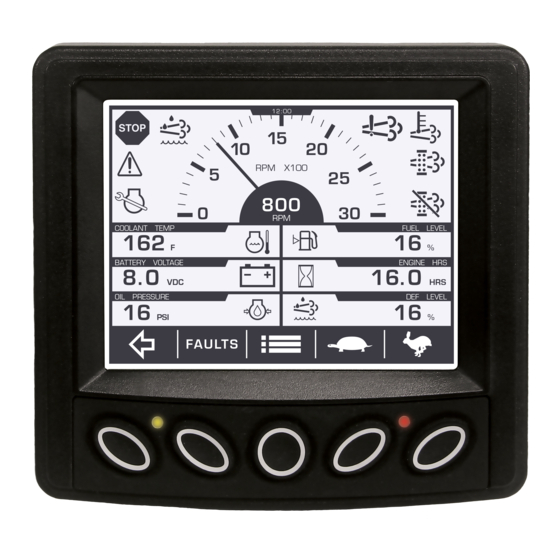
Parameter Gauge Settings 1. Alert and Warning Icon area: Up to eight symbols can be shown at one time in the icon area to represent warnings, Tier 4 status and service indicators. The most important symbol will be shown in the upper left area. The following symbols can be shown in this area: Icon(s) Function(s) -
Page 11: Adjusting Menu Selections
2. Tachometer Area: Displays the engine speed gauge with an option to choose a 3000, 4000 or 6000 RPM dial (See Display Setup on page 18 for more information). 3. Parameter Area: The following parameters are the electronic engine defaults until other parameters are selected from the menu. - Page 12 Language Follow these steps to change the Language: 1. Press to display the Menu. 2. Arrow to USER SETTINGS and then press to enter, then arrow to LANGUAGE. 3. Press to cycle through the available languages (English, French, German, Spanish and Italian).
- Page 13 Time Follow these steps to adjust the Time: 1. Press to display the Menu. 2. Arrow to USER SETTINGS. Press and then arrow to TIME. The cursor will be beneath the hour. 3. Press to adjust the selection. 4. To adjust the minutes, press , and the cursor will move to the right.
-
Page 14: Service Reminders
Clock Follow these steps to display or hide the Clock: 1. Press to display the Menu. 2. Arrow to USER SETTINGS. Press and then arrow to CLOCK. to alternate between SHOW and HIDE. 3. Press 4. Press to save and exit the menu. Service Reminders Available service reminders: Engine Oil, Fuel Filter, Engine Air Filter, Hydraulic Oil, Service Engine and Service Machine. -
Page 15: Regen
Regen Follow these steps to initiate a Regen: 1. Press to display the Menu. 2. Press to Regen. Press to enter. 3. Press once more on Request DPF Regen. 4. In answer to the question “Request Diesel Particulate Filter Regen?” use Key 3 for Yes and Key 5 for No. -
Page 16: Set Points
3. The first screen will display configured Shutdowns and the specified criteria. Press to view the second screen listing Warnings and the specified limits. Software Version To display the software version information (useful for Enovation Controls’ personnel to identify which configuration the customer is using), follow these steps: Press to display the Menu. -
Page 17: System Settings
System Settings Follow these steps to enter System Settings: Press to display the Menu. Press to System Settings. Press to enter. Utilize keys 1, 2 and 3 to input the password (3482) and press to enter the category. Engine Setup Use the following to configure engine settings. - Page 18 Engine Specific Parameters Available Type Speed Calibration Mechanical Overspeed o Shutdown % Over High Speed Fault at High Speed o Warning % Over High Speed Fault at High Speed o Disabled Machine Hours o Set Machine Hours o Clear Machine Hours Throttle Setup...
- Page 19 Inputs Follow these steps to change the Inputs: Press to display the Menu. Press to System Settings. Press to enter. Utilize keys 1, 2 and 3 to input the password (3482) and key 5 to enter. Arrow to highlight Inputs. Press to enter.
-
Page 20: Display Setup
Display Setup Follow these steps to change the Display Setup: Press to display the Menu. Press to System Settings. Press to enter. Utilize keys 1, 2 and 3 to input the password (3482) and key 5 to enter. Arrow to highlight Display Setup. Press to enter. -
Page 21: Advanced Settings
power cycle, and all previous customized settings will be restored to the original default settings. Service Reminders Follow these steps to view and reset Service Reminders: Press to display the Menu. Press to System Settings. Press to enter. Utilize keys 1, 2 and 3 to input the password (3482) and to enter. - Page 22 Available Options 0 – Override Disabled 1 – Speed Control (Eng Override Control Mode) 0 – Transient Optimized for driveline disengaged and non-lockup 696 (Eng Req Speed Control conditions* 1 – Stability Optimized for driveline disengaged and non-lockup Conditions) conditions* 2 –...
-
Page 23: Faults
Faults Follow these steps to display the Active Faults: Press FAULTS on the main page to display active faults. The following screen will appear: Press the to scroll through additional messages if any are present. Each saved code shows the SPN (Suspect Parameter Number), FMI (Failure Mode Identifier) and OC (Occurrence Count). -
Page 24: Indicator Lamps
Indicator Lamps On each gauge screen and menu (where space allows), the following indicator lamps shall be shown: Icon Description Stop Diagnostic Lamp: indicates an active DM1 stop fault Warning Diagnostic Lamp: indicates an active DM1 fault 64892 3698 High Exhaust Temperature (HEST) lamp: indicates regeneration in process 64892 3697... - Page 25 Description Icon Total Vehicle Distance 65248 VEH DIST Total Engine Hours 65253 ENG HRS Trip Fuel 65257 TRIP FUEL Total Fuel Used 65257 FUEL USED Engine Coolant Temperature 65262 Fuel Temperature 65262 Engine Oil Temperature 65262 Engine Intercooler Temp 65262 INTC TEMP Fuel Delivery Pressure 65263...
- Page 26 Description Icon Air Filter Dif. Pressure 65270 Exhaust Gas Temperature 65270 Alternator Potential 65271 ALT VOLT Electrical Potential 65271 Battery Potential Voltage 65271 Transmission Oil Pressure 65272 Transmission Oil Temp 65272 Fan Drive 65213 Auxiliary Temperature 65164 AUX TEMP Auxiliary Pressure 65164 AUX PRES Selected Gear...
- Page 27 Description Icon 65253 Total Engine Revolutions ENG REVOLU 65256 Requested Gear REQ GEAR 65276 Fuel Level 61448 Hydraulic Pressure 65128 Hydraulic Temp 61444 Machine Hours 65110 Diesel Exhaust Fluid Level DEF LVL 64891 % Soot % SOOT 64891 % Ash % ASH 64947 Exhaust Filter Temp...
-
Page 28: Specifications
Specifications Electrical 3.8” (9.65 cm) QVGA (320x240 pixels); monochrome transflective Display LCD with heater, MTFB 50,000 hours Resolution QVGA, 320 x 240 pixels Backlighting White LED (1) CAN 2.0B (J1939 protocol and proprietary messaging), (1) RS- Communications 485 serial (Modbus) Protocols J1939, NMEA 2000 Connection... - Page 29 - THIS PAGE INTENTIONALLY LEFT BLANK - Section 78 00-02-0997 (web only) 2019-10-07 - 27 -...
Need help?
Do you have a question about the Murphy PowerView PV380-R2 and is the answer not in the manual?
Questions and answers