Marantz PM-12 SE - Integrated Amplifier Manual
- Service manual (57 pages) ,
- Owner's manual (31 pages)
Advertisement
- 1 Accessories
- 2 About the remote control
- 3 Features
- 4 Part names and functions
-
5
Connections
- 5.1 Connecting speakers
- 5.2 Connecting a playback device
- 5.3 Connecting a recording device
- 5.4 Connecting multiple PM-12 SE units (F.C.B.S. connection)
- 5.5 Connecting a pre-amplifier
- 5.6 Connecting devices with remote control connectors
- 5.7 Connecting the power cord
-
6
Playback
- 6.1 Turning the power on
- 6.2 Selecting the input source
- 6.3 Adjusting the volume
- 6.4 Turning off the sound temporarily (Muting)
- 6.5 Adjusting the volume balance (LEVEL) and sound quality (BASS/TREBLE)
- 6.6 Switching the display's brightness
- 6.7 Having the illumination lamp off
- 6.8 Playing CDs
- 6.9 Recording
- 6.10 Having the illumination lamp off
- 7 Settings
- 8 Tips
- 9 Troubleshooting
- 10 Error messages
- 11 Explanation of terms
- 12 Specifications
- 13 Documents / Resources
Accessories
Check that the following parts are supplied with the product.

About the remote control
Inserting the batteries
- Remove the rear lid in the direction of the arrow and remove it.
![]()
- Insert two batteries correctly into the battery compartment as indicated.
![]()
- Put the rear cover back on.


 NOTE
NOTE
- To prevent damage or leakage of battery fluid:
- Do not use a new battery together with an old one.
- Do not use two different types of batteries.
- Remove the batteries from the remote control unit if it will not be in use for long periods.
- If the battery fluid should leak, carefully wipe the fluid off the inside of the battery compartment and insert new batteries.
Operating range of the remote control unit
Point the remote control unit at the remote sensor when operating it.

Features
High quality sound
- HDAM®SA3 Module
The HDAM® SA3 is a key amplifier module for current feedback amplifiers. It is installed in the voltage to current converter, the most crucial component, to improve the stability of the circuit and provide high-speed sound. - Linear Control Volume
The HDAM®SA3 is combined with a JRC volume IC to achieve low distortion and high S/N. A range of volumes between 0 and -99.5 dB can be smoothly controlled in ±0.5 dB steps. - Hypex Switching Power Amplifier Module
The power amplifier contains a Hypex NCore® switching power amplifier module. This switching amplifier module minimizes distortion from bass to treble and frequency characteristics are not changed by the impedance of the speakers, achieving extremely high performance. It can be used with a high-speed pre-amplifier circuit containing the HDAM® SA3 to faithfully and precisely convey the finely detailed information in DSD and high-resolution sound sources. - Marantz Musical Premium Phono EQ
The new Marantz Musical Premium Phono EQ phono equalizer has been developed for MM/MC cartridges to produce rich sound that is more similar to analog. This circuit contains a new feedbackless equalizer amplifier and MC head amplifier developed by HDAM. J-FET input is used, enabling the input coupling condenser to be eliminated. This improves the purity of the signal path in the small signal section. - High Sound Quality Parts Employed
High sound quality parts are used in every part of the circuit, including high sound quality MELF resistors and film capacitors. - Double-layered chassis
- High-grade copper machined analog audio input connectors (CD/PHONO only)
- High-grade Machined Copper Speaker Terminals
High performance
- F.C.B.S.
A Floating Control Bus System (F.C.B.S.) enables the user to connect up to four PM-12 SE units, making a diversity of applications possible with complete bi-amp and multichannel connections. Moreover, a ground loop is not formed among multiple PM-12 SE units connected; therefore, sound quality is not adversely affected. - Bi-amp mode
Complete bi-amp connection proposed by Marantz enables a level of reproduction of the acoustic field never before achieved. Synchronized operation of two PM-12 SE units is made possible by F.C.B.S. (Floating Control Bus System) connection, with each PM-12 SE in Bi-Amp mode working as a monaural integrated amplifier. - Power Amplifier Mode
In this mode, this unit works as a power amplifier. - Tone Control Amplifier
An electronic tone control amplifier is used to adjust the bass and treble volumes in 1 dB steps within a ±6 dB range.
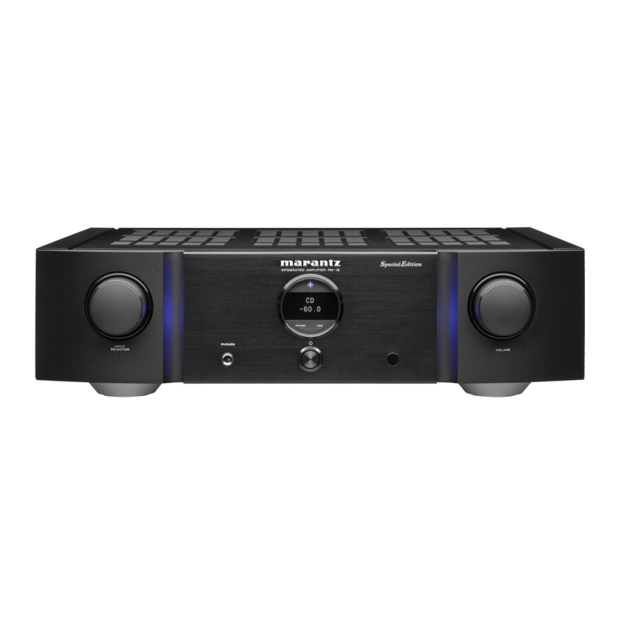
Part names and functions
Front panel

- INPUT SELECTOR knob
This selects the input source. - Illumination lamp
The illumination lamp lights (blue). - Display
This displays various pieces of information. - Power indicator
This is lit as follows according to the power status:- Power on: Blue
- Standby: Off
- Power off: Off
- STANDBY indicator
This is lit as follows according to the power status:- Power on: Off
- Standby: Red
- Power off: Off
- TONE indicator
A blue lamp lights when tone control is turned on. - VOLUME knob
These adjust the volume level. - Headphones jack (PHONES)
Used to connect headphones.
When the headphones are plugged into this jack, audio will no longer be output from the speaker terminals.
![warning]() NOTE : To prevent hearing loss, do not raise the volume level excessively when using headphones.
NOTE : To prevent hearing loss, do not raise the volume level excessively when using headphones. - Power operation button (
![]() )
)
This turns the power on/off. - Remote control sensor
This receives signals from the remote control unit.
 )
)Rear panel

- Analog audio input connectors (AUDIO IN)
Connecting to a device with analog audio output connectors.- "Connecting a playback device"
- "Connecting a recording device"
- Analog audio output connectors (AUDIO OUT)
Used to connect the input connector of a recorder. - Power amplifier connectors (POWER AMP IN)
Used to connect a pre-amplifier when this unit is used as a power amplifier. - Speaker terminals (SPEAKERS)
Used to connect speakers. - Remote control input/output connectors (REMOTE CONTROL)
Used to connect to a Marantz audio device that is compatible with the remote control function. - AMP MODE switch
Used to switch the amplifier mode (STEREO/BI- AMP). - SIGNAL GND terminal
Used to connect the ground wire of a turntable. - F.C.B.S. connectors
Used to connect a high quality playback system using two or more of PM-12 SE units. - AC inlet (AC IN)
Used to connect the power cord. - F.C.B.S. ID button
Used to set the ID number for F.C.B.S.
Remote control unit
The supplied remote control can be used to control a Marantz CD player in addition to this unit.
- "CD player operations"
Operating this unit
To operate amplifier, press REMOTE MODE AMP button to switch the remote control to the amplifier operation mode.

- Remote control signal transmitter
This transmits signals from the remote control unit. - Cursor buttons (
![]() )
)
These select items. - DISPLAY button
Each press of this switches the brightness of the display.
Press and hold to turn the illumination lamp on/off. - Input source select buttons (INPUT
![]() )
)
This selects the input source. - Power operation button (
![]() AMP)
AMP)
This turns the power on/off (standby). - Remote mode select button (REMOTE MODE AMP)
This switches the remote control to amplifier control mode. - ENTER button
This determines the selection. - SETUP button
This displays the setting menu on the display. - MODE/TRIM button
This displays the volume balance adjustment menu on the display. - TONE button
Turns the tone control function on/off. - VOLUME buttons (
![]() )
)
These adjust the volume level. - MUTE button
This mutes the output audio.
 )
) )
)CD player operations
To operate a Marantz CD player, press the REMOTE MODE CD button to switch the remote control to the CD player operation mode.

- Power operation button (
![]() CD)
CD) - Remote mode select button (REMOTE MODE CD)
- Cursor buttons (
![]() )
) - DISPLAY button
- System buttons
- Information button (INFO)
- Number buttons (0 – 9, +10)
- RANDOM button
- REPEAT button
- FILTER button
- SOUND MODE button
- ENTER button
- SETUP button
- MODE/TRIM button
- OPEN/CLOSE button
- DISC/INPUT button
- CLEAR button
- PROGRAM button
- DIGITAL OUT button

- Basic amplifier operations such as switching the input source, trimming the volume and muting can be done even when CD is set as the remote control operation mode.
- When using it, also refer to the operating instructions of the other devices.
- The remote control may not operate some products.
Connections
NOTE
- Do not plug in the power cord until all connections have been completed.
- Do not bundle power cords together with connection cables. Doing so can result in humming or noise.
Cables used for connections
Provide necessary cables according to the devices you want to connect.
Speaker cable |
Audio cable |
Remote connector cable |
Connecting speakers
NOTE
- Disconnect this unit's power plug from the power outlet before connecting the speakers.
- Connect so that the speaker cable core wires do not protrude from the speaker terminal. The protection circuit may be activated if the core wires touch the rear panel or if the + and - sides touch each other. ("Protection circuit" )
- Never touch the speaker terminals while the power cord is connected. Doing so could result in electric shock.
- Use speakers with an impedance of 4 – 16 Ω/ohms.
Connecting the speaker cables
Carefully check the left (L) and right (R) channels and + (red) and - (white) polarities on the speakers being connected to this unit, and be sure to connect the channels and polarities correctly.
- Peel off about 10 mm of sheathing from the tip of the speaker cable, then either twist the core wire tightly or terminate it.
![]()
- Turn the speaker terminal counterclockwise to loosen it.
![]()
- Insert the speaker cable's core wire to the hilt into the speaker terminal.
![]()
- Turn the speaker terminal clockwise to tighten it.
![]()
Spade lug connector
![]()


Speaker connection

Connecting a playback device
You can connect turntables, tuners, CD players and network audio players to this unit.
Set the phono equalizer of this unit in the "PHONO" section of the setting menu according to the type of turntable cartridge to be connected.
If you set this unit's input source to "PHONO" and you accidentally increase the volume without having a turntable connected, you may hear a hum noise from the speakers.

NOTE
The earth terminal (SIGNAL GND) of this unit is not for safety grounding purposes. If this terminal is connected when there is a lot of noise, the noise can be reduced. Note that depending on the turntable, connecting the ground line may have the reverse effect of increasing noise. In this case, it is not necessary to connect the ground line.
The PHONO input terminals are equipped with a short pin-plug.
Remove this plug to connect a record player. Store the removed short pin-plug in a safe place so as not to lose it.
Connecting a recording device

NOTE
Never insert the short-circuiting pin plug into the recording output connectors (AUDIO OUT RECORDER). Doing so could result in damage.
Connecting multiple PM-12 SE units (F.C.B.S. connection)
The Marantz F.C.B.S. (Floating Control Bus System) is the high quality sound system for link control between multiple PM-12 SE units (up to 4 units). Each unit is controlled via its ID number registered beforehand. The ID numbers need to be set to an operating unit (master) and a subordinate unit (slave) receiving the command from the master. For slave units, register ID numbers in the order of command reception from the master.
ID numbers can be set for units connected by F.C.B.S. to perform linked operations such as switching the input source, adjusting the volume, muting, adjusting the volume balance, adjusting the sound quality and trimming the display brightness.
Furthermore, F.C.B.S. connection of multiple PM-12 SE units has the feature that switches this unit's output from stereo to monaural so that the unit can works as a monaural output amplifier. Follow the respective instructions to make the necessary settings.
Preparation for F.C.B.S. connection
Making the F.C.B.S. connection
To use multiple PM-12 SE units, make this connection in addition to audio connection. For details on each connection feature, refer to the respective instructions.
- "Stereo complete bi-amp connection"
- "Connection for 5.1 Multi-channel Playback"
Prepare the correct number of portable audio connection cables for the number of units to be connected. Either of the following types of connection cables are adequate.
- Φ3.5 Monaural mini plug ←→ Φ3.5 monaural mini plug connecting cable
![]()
- Φ3.5 Stereo mini plug ←→ Φ3.5 stereo mini plug connecting cable
![]()


NOTE: Do not use connecting cables that contain resistance.
Connection example
In the connection of the following example, an unit with ID number 1 acts as a master amplifier to control all the other slave units with ID numbers 2 to 4.

- The PM-12 SE F.C.B.S. function is only valid between the same PM-12 SE models.
- To turn the power of multiple F.C.B.S.-connected units ON/ OFF, switch the power ON in order of lowest to highest ID number, and switch the power OFF in order of highest to lowest ID number.
How to set ID number for F.C.B.S.

- While holding F.C.B.S. ID on the rear panel, press
![]() .
. - Turn INPUT SELECTOR on the unit to select an ID number.
- For a master unit, ID number 1 needs to be assigned. For a slave unit, set any of ID numbers 2 to 4.
- Again turn the unit on.
The ID number appears on the display for around 3 seconds.- The setting is saved.
- The unit registered as a slave shows "SLAVE" on the display.
 .
.
- If using this unit by itself as a stereo amplifier, set the ID number to "0". (Default setting is "0".)
- If the ID number is set to a number other than "0", this unit cannot be used for standalone operation.
Stereo complete bi-amp connection
This mode enables the two amplifiers connected to this unit to function as one monaural amplifier. To use this mode, two F.C.B.S. connected PM-12 SE units are required.
To switch the mode, use the AMP MODE switch on the rear panel while the power is off.
If this unit is set to the bi-amp mode, "BI-AMP" appears on the display.
In bi-amp mode, connect to the left channel input connector. The right channel input is disabled.
The same signals are output from the left and right speaker terminals.
- Be sure to turn the power off before operating the AMP MODE switch. Settings can be configured when the power is turned on.
- When in bi-amp mode, the R channel input connectors cannot be used.
- When in bi-amp mode, the signals input into the L channel are output from both channels. Therefore, the same signals are output from the L channel and R channel in RECORDER OUT, headphones jack.
- Speaker systems connected using complete bi-amp connections must support bi-amp connections. Before connecting your speakers, check in the instruction manual that came with the speakers or contact the manufacturer to confirm whether they support bi-amp connection.

Connection for 5.1 Multi-channel Playback
Three PM-12 SE units can be connected by F.C.B.S. and used through linked operation. For details on F.C.B.S. connection, see "Examples of Connections".
Connect the outputs of players that have 5.1 channel analog outputs to each of the three units.
If using an active subwoofer, see the instruction manual that came with the subwoofer for further instructions.
Set the ID numbers for the three amplifiers as explained in How to set ID number for F.C.B.S.
- When the ID 1 unit is operated, ID 2 and ID 3 units will operate in sync.

Speaker Positioning for Super Audio Multi-channel Sound
In order to enjoy Super Audio CD multi-channel sound with the best possible acoustics, it is recommended to position speakers as specified in ITU-R BS.775-1 of the International Telecommunication Union (ITU). Super Audio CD multichannel discs are recorded and mixed so as to achieve the optimum effect with a speaker system laid out as specified in ITU-R BS.775-1.
- With Super Audio CD multi-channel discs, the music signals are basically recorded using 5 channels (3 - 6 channels sometimes), but in some cases, LFE (for subwoofer) is recorded as a sixth channel.
- Each disc indicates how many channels have been recorded on it.
- The basic layout is 3 speakers in the front and 2 in the back since multi-channel discs usually have 5 channels. The 2 front, 1 center and 2 surround (rear) speakers should be set in a circle around the listening point. If using speakers of differing sizes, adjust volume balance from the amplifier.
- The location of the subwoofer in the figure is just for explanatory purposes. It can be located anywhere in the room. For connection and positioning instructions, see the instruction manual that came with the subwoofer.

- ITU (International Telecommunication Union)
The ITU is a special organization of the United Nations. It consists of a number of organs, one of which is the Radio Broadcasting Section.
ITU-R BS in the recommendation which consists of standards relating to broadcasting (audio) operations, one of which is the ITU-R BS.775-1 which governs "multi-channel stereo sound systems".
Connecting a pre-amplifier
If you use a pre-amplifier, connect it as shown below, and then you can use this unit as a power amplifier.

- Turn INPUT SELECTOR on the main unit to select the input source to "PWR AMP".
- You cannot use the input source switching buttons on the remote control unit to select "PWR AMP".
- Volume adjustment, muting and adjustments to the volume balance (LEVEL) and sound quality (BASS/TREBLE) are not possible when the input source is "PWR AMP". Adjust these via the pre-amplifier connected to this unit.
- When the input source is set to "PWR AMP", you cannot use the remote control unit to select the input source.
NOTE: When the input source is "PWR AMP", the main unit outputs at maximum volume. Check the output level on the input device before playing it and adjust the volume accordingly.
Connecting devices with remote control connectors
Performing operations by RC on this unit without visual contact
You can connect an external IR receiver to the REMOTE CONTROL connectors to perform operations on this unit with the supplied remote control unit without visual contact. This might be necessary if the unit is hidden in a cupboard or corner, so you can't directly point with the remote control unit to the device.

Remotely connecting Marantz audio devices
You can transmit remote control signals simply by connecting a Marantz audio device to the REMOTE CONTROL IN/OUT connectors using the remote connection cable provided with the device.
Set the remote control switch located on the rear panel of the connected audio component to "EXTERNAL" to use this feature.

Connecting the power cord
After completing all the connections, insert the power plug into the power outlet.

Playback

Turning the power on
- Press
![]() on the main unit to turn the power on.
on the main unit to turn the power on. - The power indicator lights in blue.
 on the main unit to turn the power on.
- Press
![]() AMP on the remote control unit to turn on power from standby mode.
AMP on the remote control unit to turn on power from standby mode. - You can also turn the INPUT SELECTOR on the main unit when the unit is in standby mode to turn on the power.
Switching the power to standby
- Press
![]() AMP on the remote control.
AMP on the remote control.
The unit switches to standby mode, and the STANDBY indicator lights red.
NOTE
- Power continues to be supplied to some of the circuitry even when the power is in the standby mode. When leaving home for long periods of time or when going on vacation, either press
![]() on the main unit to turn off the power, or unplug the power cord from the power outlet.
on the main unit to turn off the power, or unplug the power cord from the power outlet.
Selecting the input source
- Use INPUT
![]() to select the input source to be played back.
to select the input source to be played back.
The selected input source appears on the display.
 to select the input source to be played back.
 You can also select the input source by turning INPUT SELECTOR on the main unit.
Adjusting the volume
- Use VOLUME
![]() to adjust the volume.
to adjust the volume.
You can also adjust the volume by turning VOLUME on the main unit.
Turning off the sound temporarily (Muting)
- Press MUTE.
"MUTE" appears on the display and the sound is muted.
- To cancel mute, press MUTE again.
- You can set the volume to be decreased when MUTE is pressed. Set this as desired through "ATT LEVEL" in the menu.
Adjusting the volume balance (LEVEL) and sound quality (BASS/TREBLE)
Adjusting LEVEL
The volume level of the left and right channels can be trimmed in 0.5 dB steps across a 0.0 - -9.0 dB range. The factory default setting is 0.0 dB (maximum).
- Press MODE/TRIM.
The unit enters LEVEL adjustment mode.- If the slave is connected by F.C.B.S., the device for to adjust the volume balance (LEVEL) and sound quality (BASS/TREBLE) can be switched by pressing this button.
- Use
![]() to select the channel that you wish to 2 configure (L or R).
to select the channel that you wish to 2 configure (L or R).
The level value of the selected channel flashes. - Use
![]() to adjust the volume.
to adjust the volume.
![information]() If there is no operation for 15 seconds, the setting is committed and the unit returns to the standard display.
If there is no operation for 15 seconds, the setting is committed and the unit returns to the standard display. - Press ENTER.
This exits LEVEL adjustment mode and enters BASS adjustment mode. Follow steps 3 onward of "Adjusting BASS" to adjust the bass.
 to select the channel that you wish to 2 configure (L or R).
 to adjust the volume.
Adjusting BASS
The bass volume can be adjusted in 1 dB steps across a -6 - +6 dB range. The factory default setting is 0 dB.
- Press MODE/TRIM.
The unit enters LEVEL adjustment mode. - Press ENTER to select "BASS".
The unit enters BASS adjustment mode. - Use
![]() to adjust the bass volume.
to adjust the bass volume.
![information]() If there is no operation for 15 seconds, the setting is committed and the unit returns to the standard display.
If there is no operation for 15 seconds, the setting is committed and the unit returns to the standard display. - Press ENTER.
This exits BASS adjustment mode and enters TREBLE adjustment mode. Follow steps 3 onward of "Adjusting TREBLE" to adjust the treble.
Settings are not applied when tone control is turned off. Press TONE to turn on tone control (TONE indicator lights).
Adjusting TREBLE
The treble volume can be adjusted in 1 dB steps across a -6 - +6 dB range. The factory default setting is 0 dB.
- Press MODE/TRIM.
The unit enters LEVEL adjustment mode. - Press ENTER twice to select "TREBLE".
The unit enters TREBLE adjustment mode. - Use
![]() to adjust the treble volume.
to adjust the treble volume.
![information]() If there is no operation for 15 seconds, the setting is committed and the unit returns to the standard display.
If there is no operation for 15 seconds, the setting is committed and the unit returns to the standard display. - Press ENTER.
This exits TREBLE adjustment mode and returns to the normal display.
Settings are not applied when tone control is turned off. Press TONE to turn on tone control (TONE indicator lights).
Switching the display's brightness
The display brightness can be adjusted between four levels.
Switching the display off reduces a source of noise that affects sound quality, enabling higher sound quality playback.
- Press DISPLAY.
The brightness of the display switches each time DISPLAY is pressed.
- The display brightness is set to most brightly by default.
- If you operate the VOLUME knob or another control when the display is off, the display turns on again. When operation is finished, the display turns off automatically after approximately 2 seconds.
- When the display brightness is set to off, the illumination lamp turns off too.
Having the illumination lamp off
- Press and hold DISPLAY for 2 seconds or more while the illumination lamp is lit.
Press and hold DISPLAY for two seconds and longer while the lamp is always off to return to the normal setting.
Playing CDs
This section uses playback from a CD as an example.
- Press
![]() on the main unit to turn the power on.
on the main unit to turn the power on. - Use INPUT
![]() to switch the input source to "CD".
to switch the input source to "CD".
"CD" appears on the display. - Playback the CD.
- Use VOLUME
![]() to adjust the volume.
to adjust the volume.
 on the main unit to turn the power on.
  to switch the input source to "CD".
Recording
Audio signals input into this unit can be output to an external recording device. When recording audio from a playback device connected to this unit, audio can be recorded with the playback device still connected to this unit.
- Press
![]() on the main unit to turn the power on.
on the main unit to turn the power on. - Use INPUT
![]() to switch to the input source 2 from which you want to record.
to switch to the input source 2 from which you want to record.
The selected input source is displayed on the display. - Recording starts.
- For information on operations, see the owner's manual of the recording device.
 on the main unit to turn the power on.
 to switch to the input source 2 from which you want to record.
Having the illumination lamp off
- Press and hold DISPLAY for 2 seconds or more while the illumination lamp is lit.
Press and hold DISPLAY for two seconds and longer while the lamp is always off to return to the normal setting.
Settings
Menu map
By default, this unit has recommended settings defined. You can customize this unit based on your existing system and your preferences.
| Setting items | Description |
| PHONO | Sets the phono equalizer of this unit according to the type of the turntable cartridge to be connected. |
| AUTO STBY (Auto Standby) | Sets whether to automatically switch the unit to the standby mode when there is no audio input and no operations are performed for more than 30 minutes. |
| ATT LEVEL (Attenuation Level) | Sets how far the volume is decreased when the MUTE button is pressed. |
Menu operation

- Press SETUP.
The menu is displayed on the display. - Use
![]() to select the menu to be set or operated, then press ENTER.
to select the menu to be set or operated, then press ENTER. - Use
![]() to change to desired setting.
to change to desired setting. - Press ENTER to enter the setting.
- To return to the previous item, press
![]() .
. - Exiting the Menu, press SETUP while the menu is displayed. The display returns to the normal display.
- To return to the previous item, press

PHONO
Sets the phono equalizer of this unit according to the type of the turntable cartridge to be connected.
| MM (Default): | Set this for an MM cartridge. |
| MC: | Set this for an MC cartridge. |
NOTE: The audio is muted for around 4 seconds when this setting is changed.
AUTO STBY (Auto Standby)
Sets whether to automatically switch the unit to the standby mode when there is no input signal and operation for 30 minutes.
| ON (Default): | Enable Auto Standby mode. |
| OFF: | Disable Auto Standby mode. |
- The display will show the remaining time for three minutes before the units enters standby mode.
- In F.C.B.S. connection, only the ID 1 master unit activates Auto Standby mode. If the ID 1 master unit is operated with no audio input, set the Auto Standby mode to off.
ATT LEVEL (Attenuation Level)
Sets how far the volume is decreased when the MUTE button is pressed.
-20 dB / -40 dB / -∞(Default: -∞)
- "ATT" appears on the display if the MUTE button is pressed when -20 dB or -40 dB is set.
- "MUTE" appears on the display if the MUTE button is pressed when -∞ is set.
- Press the MUTE button again to cancel the setting and return to the original volume.
Tips
I want to set how far the volume is decreased when the MUTE button is pressed
- 20 dB, -40 dB or - ∞ can be set.
I want to turn the illumination lamps on both sides of the unit main panel off
- Set the illumination lamp to off.
I want to use two or more of PM-12 SE units for high quality playback
- Use the stereo complete bi-amp connections.
- Use the multi-channel playback connections.
I want to use this unit's remote control to operate a Marantz CD player
- Press the REMOTE MODE CD button to switch the remote control to the CD player operating mode.
- Also, refer to the instruction manual of the CD player.
I want to use this unit as a power amplifier
- Connect the pre amplifier to the POWER AMP IN connectors of this unit.
Troubleshooting
If a problem should arise, first check the following:
- Are the connections correct?
- Is the set being operated as described in the owner's manual?
- Are the other devices operating properly?
If this unit does not operate properly, check the corresponding symptoms in this section.
If the symptoms do not match any of those described here, consult your dealer as it could be due to a fault in this unit. In this case, disconnect the power immediately and contact the store where you purchased this unit.
Power does not turn on / Power is turned off
| Symptom | Cause / Solution |
| Power is not turned on. |
|
| Power automatically turns off. |
|
| Power turns off and the STANDBY indicator flashes in red approx. every 0.5 seconds. |
|
| |
| |
| |
|
Operations cannot be performed through the remote control unit
| Symptom | Cause / Solution |
| Operations cannot be performed through the remote control unit. |
|
| |
| |
| |
| |
| |
|
No sound comes out
| Symptom | Cause / Solution |
| No sound comes out of speakers. |
|
| |
| |
| |
| |
| |
| |
| |
| |
|
Desired sound does not come out
| Symptom | Cause / Solution |
| No sound comes out of a specific speaker. |
|
| |
| The left and right of stereo sound is reversed. |
|
Sound is interrupted or noise occurs
| Symptom | Cause / Solution |
| When playing a record, the sound is distorted. |
|
| |
| |
| When playing a record, a humming noise comes out of the speakers. |
|
| |
| When playing a record, a humming noise comes out of the speakers when the volume is high. (Howling phenomenon) |
|
| |
| Audio sources recorded through this unit are distorted. |
|
Error messages
When multiple PM-12 SE units are connected by F.C.B.S., the error messages described in the table below may be displayed on the display. In such a case, ID number setting or remote cable connection may be in failure. Check the ID number or remote cable connection, referring to the table below. For details on ID number setting, see "How to set ID number for F.C.B.S."
| Indication | Meaning | Cause / Solution |
| ERROR 02 | Multiple amplifiers take ID No.2. |
|
| ERROR 03 | Multiple amplifiers take ID No.3. | |
| ERROR 04 | Multiple amplifiers take ID No.4. | |
| ERROR 11 | The amplifiers with ID No.2-4 cannot communicate with the amplifier with ID No.1. |
|
| ERROR 12 | The amplifier with ID No.1 cannot communicate with the amplifiers with ID No.2-4. |
|
Explanation of terms
MM/MC cartridge
There are two types--MM (Moving Magnet) and MC (Moving Coil)--of cartridges for turntable. As the output levels for these two types of cartridges differ, the setting of the phono equalizer that is mounted in this unit must be switched according to the type of cartridge for your turntable. Change this setting in the "PHONO" section of the setting menu.
Speaker impedance
This is an AC resistance value, indicated in Ω (ohms).
Greater power can be obtained when this value is smaller.
Protection circuit
This is a function to prevent damage to devices within the power supply when an abnormality such as an overload, excess voltage occurs or over temperature for any reason.
Specifications
| RMS Power output (Simultaneous drive of both channels): | 100 W x 2 (8 Ω/ohms load, 1 kHz, T.H.D. 0.05%) 200 W x 2 (4 Ω/ohms load, 1 kHz, T.H.D. 0.1%) |
| Total harmonic distortion (1 kHz, simultaneous drive of both channels, 100 W, 8 Ω/ohms load): | 0.005% |
| Frequency response (CD, 1 W, 8 Ω/ohms load): | 5 Hz – 50 kHz ±3 dB |
| Damping factor (8 Ω/ohms load, 20 Hz – 20 kHz): | 500 |
| Input sensitivity/Input impedance | |
| 250 μV / 100 Ω/ohms |
| 2.3 mV/39 kΩ/kohms |
| 220 mV/13 kΩ/kohms |
| 1.1 V/13 kΩ/kohms |
| Maximum allowable PHONO input level (1 kHz) | |
| 8 mV |
| 80 mV |
| ±0.5 dB |
| S/N (IHF-A, 8 Ω/ohms load) | |
| 75 dB (0.5 mV Input) |
| 88 dB (5 mV Input) |
| 107 dB (Rated output) |
| Tone Control | |
| ±6 dB |
| ±6 dB |
| Power supply: | AC 230 V, 50/60 Hz |
| Power consumption: | 130 W |
| Power consumption in standby mode: | 0.2 W |
For the purpose of improvement, the specifications and design are subject to change without notice.
Dimensions (Unit: mm)
")
* Weight: 15.3 kg
Documents / Resources
References
Download manual
Here you can download full pdf version of manual, it may contain additional safety instructions, warranty information, FCC rules, etc.
Advertisement


Need help?
Do you have a question about the PM-12 SE and is the answer not in the manual?
Questions and answers