Table of Contents
Advertisement
Quick Links
MU524 Assembly guide
Safety warning
The kits are main powered and use potentially lethal voltages. Under no circumstance should someone undertake the
realisation of a kit unless he has full knowledge about safely handling main powered devices.
Please read the "DIY guide" before beginning.
Print or open the following documents:
• MU524 Schematics
• MU524 Components layout
• MU524 Parts list
Follow this guide from item number 1 till the end, in this order. The assembly order is based on components height, from
low to high profile, in order to ease the soldering process : The component you are soldering is always taller than the
previously assembled ones and it is pressing nicely against the work area foam.
Soldering
All the PCB holes are metallized. It means the connection between the top and bottom pads is already
done. The parts must be soldered only from below (unless differently stated).
Use only small diameter solder, 0.5 or 0.7 mm, 1mm maximum. Use the minimum possible amount of
solder. Bad joints are almost always caused by too much solder.
Cut the component leads and pins totally flush with the PCB after soldering. A too long tail could create
an electric connection with the side plate.
Here are two excellent introduction to soldering videos:
http://www.eevblog.com/2011/06/19/eevblog-180-soldering-tutorial-part-1-tools/
http://www.eevblog.com/2011/07/02/eevblog-183-soldering-tutorial-part-2/
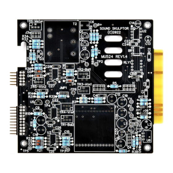
MU524 Assembly guide – Main PCB
1.
PCB split
Split the PCB into 7
parts along the
grooves. Use extra thin
sandpaper to polish all
the rough sides
Copyright ©2022 to today SoundSkulptor
Document revision 1.1 – Last modification : May 26, 2023
www.soundskulptor.com
Advertisement
Table of Contents

Related Manuals for Sound Skulptor MU524


Summary of Contents for Sound Skulptor MU524
- Page 1 Cut the component leads and pins totally flush with the PCB after soldering. A too long tail could create an electric connection with the side plate. Here are two excellent introduction to soldering videos: http://www.eevblog.com/2011/06/19/eevblog-180-soldering-tutorial-part-1-tools/ http://www.eevblog.com/2011/07/02/eevblog-183-soldering-tutorial-part-2/ MU524 Assembly guide – Main PCB PCB split Split the PCB into 7 parts along the grooves. Use extra thin...
- Page 2 Document revision 1.1 – Last modification : May 26, 2023 MU524 Assembly guide – Main PCB PCB to PCB connector J1a, J2a Insert the male 2x10 and 2x5 connectors into their places at the back of the main PCB. Solder one pin, check that the contacts are perfectly parallel to the PCB then solder the other pins.
-
Page 3: Ceramic Capacitors
Document revision 1.1 – Last modification : May 26, 2023 MU524 Assembly guide – Main PCB Ceramic capacitors Add the ceramic capacitors. Bridge rectifier Insert and solder the bridge rectifiers BR1. Warning: The direction of the bridge is identified by a beveled side and 2 signs + and – on the case and on the PCB. - Page 4 Document revision 1.1 – Last modification : May 26, 2023 MU524 Assembly guide – Main PCB Small film capacitors Add the small film capacitors C4, C7, C15. 10. Transistors and U5 Add Q1, Q2, Q3 and U5. Warning: Q3 (2N7000) is a sensitive device which can easily be destroyed by static electricity. Make sure you are not charged before manipulating it (simply work without your shoes on).
-
Page 5: Electrolytic Capacitors
Document revision 1.1 – Last modification : May 26, 2023 MU524 Assembly guide – Main PCB 13. Connector J3a Add the 2x3 pins female connector J3a 14. Large film capacitors Add the larger film capacitors C16 and C6. 15. Trimmer potentiometers Add the 6 trimmer potentiometers TR1 to TR6. - Page 6 Document revision 1.1 – Last modification : May 26, 2023 MU524 Assembly guide – Main PCB 22. Transformer T2 Stick a small piece of adhesive rubber under the transformer T2 (Z3002C) so that the metal case does not touch the PCB traces.
-
Page 7: Integrated Circuits
Document revision 1.1 – Last modification : May 26, 2023 MU524 Assembly guide – Main PCB 24. Transformer T1 front PCB Use the input transformer front PCB, the one with the pin holes and numbers. Insert the 90°, 13 pins headers, long tails first, into the holes, from the bottom side, marked “Not visible”. - Page 8 Document revision 1.1 – Last modification : May 26, 2023 MU524 Assembly guide – Main PCB 29. Fem/fem spacer Insert a M3x10mm screw from below PCB, in the upper left hole. Add an M3 nut and tighten then add a 25mm spacer and tighten.
- Page 9 Document revision 1.1 – Last modification : May 26, 2023 MU524 Assembly guide – Front PCB 31. Resistors Add R19, R24, R25, R26. The resistors on the front PCB are installed vertically. 32. Push switches Insert the push switches SW2, SW3, SW4 flat on the PCB, in the correct direction and solder one pin.
-
Page 10: Meter Connections
Document revision 1.1 – Last modification : May 26, 2023 MU524 Assembly guide – Front PCB MU524 Assembly guide – Meter assembly 37. Connector Solder the 2x3 pins header to the small meter PCB. 38. Meter connections There are 2 wire colors and 2 sizes. - Page 11 Document revision 1.1 – Last modification : May 26, 2023 MU524 Assembly guide – Final assembly 41. Chassis plate assembly Attach the chassis plate to the front plate with two M3x6mm black screws. 42. Main PCB assembly Insert the main PCB by matching the J1 and J2 connectors.
- Page 12 Document revision 1.1 – Last modification : May 26, 2023 MU524 Assembly guide – Final assembly Copyright ©2022 to today SoundSkulptor...
Need help?
Do you have a question about the MU524 and is the answer not in the manual?
Questions and answers