Advertisement
Quick Links
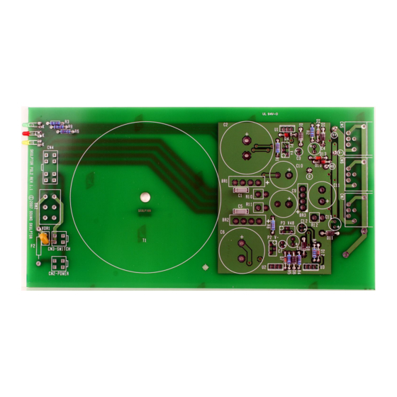
PSL2 Assembly guide
Safety warning
THIS KIT IS NOT FOR BEGINNERS !
This kit is main powered and use potentially lethal voltages. Under no circumstance should someone undertake the
realisation of this kit unless he has full knowledge about safely handling main powered devices.
Please read the "DIY guide" before beginning.
Print or open the following documents :
• PSL2 Schematic
• PSL2 Components layout
• PSL2 Parts list
• PSL2 Setup guide
Follow this guide from item number 1 till the end, in this order. The assembly order is based on components height, from
low to high profile, in order to ease the soldering process : The component you are soldering is always taller than the
previously assembled ones and it is pressing nicely against the work area foam.
PSL2 Assembly guide
1.
Diodes
Add D2, D7, D12, D1, D3, D6, D8, D11, D4, D10, D13. Use a lead forming tool to cleanly bend the
leads at 0.4".
Warning
: Make sure to respect the direction of the diodes which is marked by a ring on the component
and a double line on the PCB marking.
Warning
: Do not insert D12 in the wrong hole. It is bended at 0.4" like R7 next to it.
2.
Resistors
Add R1 to R9. Control the resistor values with a digital multimeter. Bend the leads at 0.4" with a lead
forming tool.
3.
Leds
Add D5, D9, D14
Bend the leads at 7mm from the body taking care of the anode position
(the longest lead).
Warning
: it is easy to bend the leads in the wrong direction !
Solder the LED so it rests on the board. Start by soldering one lead,
adjust the position, then solder the second lead.
4.
Test pins
Solder the 4 test pins TP1 to TP4.
Copyright ©2007 SoundSkulptor
Document revision 1.1 – Last modification : 30/05/08
www.soundskulptor.com
7.00 mm
Anode : long lead
Advertisement

Related Manuals for Sound Skulptor PSL2


Summary of Contents for Sound Skulptor PSL2
- Page 1 Please read the “DIY guide” before beginning. Print or open the following documents : • PSL2 Schematic • PSL2 Components layout • PSL2 Parts list • PSL2 Setup guide Follow this guide from item number 1 till the end, in this order. The assembly order is based on components height, from low to high profile, in order to ease the soldering process : The component you are soldering is always taller than the previously assembled ones and it is pressing nicely against the work area foam.
- Page 2 Document revision 1.1 – Last modification : 30/05/08 PSL2 Assembly guide VDR1 Add the VDR1 varistor. Film capacitors Add C1 and C5 Trimmer potentiometers Add P1, P2, P3. Solder one pin, check verticality then solder the other pins. Small electrolytic capacitors Add C3, C7, C12, C4, C8 Solder one lead first, adjust verticality then solder the second lead.
- Page 3 Document revision 1.1 – Last modification : 30/05/08 PSL2 Assembly guide 10. 115/230V Selector switch Add SW2. 11. Bridge rectifiers Add BR1, BR2, BR3. Warning : Make sure to respect the direction of the bridge rectifiers, It is marked by + and - signs.
- Page 4 Document revision 1.1 – Last modification : 30/05/08 PSL2 Assembly guide 16. Large Electrolytics Add C11, C2, C6 Solder one lead first, adjust verticality then solder the second lead. Warning : The +lead must go into the +hole. Do not reverse.
- Page 5 Document revision 1.1 – Last modification : 30/05/08 PSL2 Assembly guide 19. Earth connection Solder 4cm of black insulated wire between the pcb hole and the earth pin on the IEC connector and 2cm of bare copper wire between the same earth pin and the solder tag previously attached to the top screw of the connector.
- Page 6 Document revision 1.1 – Last modification : 30/05/08 PSL2 Assembly guide 23. Single heatsink assembly Place a drop of thermal compound on the heatsink front face, the volume of a grain of rice. The back face can be identified by the countersunk hole.
- Page 7 Document revision 1.1 – Last modification : 30/05/08 PSL2 Assembly guide 25. Transformer plate assembly Attach the transformer plate to the PCB with one M3x10 screw and one self locking nut. 26. Case assembly Assemble the front plate and the two sides of the case with four black M4 countersunk screws.
- Page 8 Document revision 1.1 – Last modification : 30/05/08 PSL2 Assembly guide 30. Back plate assembly Attach the back plate with four M4 countersunk screws. 31. Heatsinks assembly Tighten firmly the fixing screws of both heatsinks. Solder the 3 regulators. Cut the pins flush.
- Page 9 Make a full visual check. Any missing component on the board ? Any remaining component in the box ? 35. Setup Your PSL2 is now ready for test and setup. Please follow instructions in the “PSL2 Setup” document. 36. Closing the case With the help of the bottom cover, position the fixing nuts in front of the holes.
Need help?
Do you have a question about the PSL2 and is the answer not in the manual?
Questions and answers