Table of Contents
Advertisement
Quick Links
INSTRUCTION MANUAL
MECHATROLINK I/O MODULE
(high-speed DC voltage output, 4 points, isolated,
screw terminal block, MECHATROLINK-I/-II)
BEFORE USE ....
Thank you for choosing us. Before use, please check con-
tents of the package you received as outlined below.
If you have any problems or questions with the product,
please contact our sales office or representatives.
■ PACKAGE INCLUDES:
High-speed DC voltage output module ..............................(1)
DIN rail mounter slider ......................................................(2)
■ MODEL NO.
Confirm Model No. marking on the product to be exactly
what you ordered.
■ INSTRUCTION MANUAL
This manual describes necessary points of caution when
you use this product, including installation, connection and
basic maintenance procedures.
MG CO., LTD. www.mgco.jp
5-2-55 Minamitsumori, Nishinari-ku, Osaka 557-0063 JAPAN
R7G4HML-6-YVF4
MODEL
POINTS OF CAUTION
■ CONFORMITY WITH EU DIRECTIVES
• The equipment must be mounted inside the instrument
panel of a metal enclosure.
• The actual installation environments such as panel con-
figurations, connected devices, connected wires, may af-
fect the protection level of this unit when it is integrated
in a panel system. The user may have to review the CE
requirements in regard to the whole system and employ
additional protective measures to ensure the CE conform-
ity.
■ POWER INPUT RATING & OPERATIONAL RANGE
• Locate the power input rating marked on the product and
confirm its operational range as indicated below:
24V DC rating: 24V ±10%, approx. 100mA
■ GENERAL PRECAUTIONS
• Before you remove the unit or mount it, turn off the power
supply and output signal for safety.
• Before you remove the terminal block or mount it, make
sure to turn off the power supply and output signal for
safety.
• DO NOT set the switches on the module while the power
is supplied. The switches are used only for maintenance
without the power.
■ ENVIRONMENT
• Indoor use.
• When heavy dust or metal particles are present in the
air, install the unit inside proper housing with sufficient
ventilation.
• Do not install the unit where it is subjected to continuous
vibration. Do not subject the unit to physical impact.
• Environmental temperature must be within 0 to 55°C (32
to 131°F) with relative humidity within 30 to 90% RH in
order to ensure adequate life span and operation.
■ WIRING
• Do not install cables close to noise sources (relay drive
cable, high frequency line, etc.).
• Do not bind these cables together with those in which
noises are present. Do not install them in the same duct.
• Be sure to close the terminal cover for safety.
■ AND ....
• The unit is designed to function as soon as power is sup-
plied, however, a warm up for 10 minutes is required for
satisfying complete performance described in the data
sheet.
EM-7775-A Rev.3 P. 1 / 10
Advertisement
Table of Contents

Related Manuals for MG R7G4HML-6-YVF4


Summary of Contents for MG R7G4HML-6-YVF4
- Page 1 • The unit is designed to function as soon as power is sup- plied, however, a warm up for 10 minutes is required for satisfying complete performance described in the data sheet. EM-7775-A Rev.3 P. 1 / 10 MG CO., LTD. www.mgco.jp 5-2-55 Minamitsumori, Nishinari-ku, Osaka 557-0063 JAPAN...
-
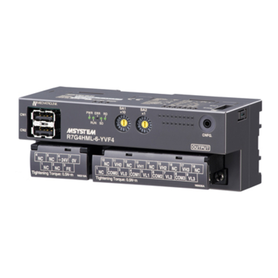
Page 2: Component Identification
MECHATROLINK-II (32 byte mode) MECHATROLINK-I (17 byte mode) Station Address Setting (×10) Note: Be sure to set unused SW1-1 through 1-3, SW2-3 and 2-4 to OFF. EM-7775-A Rev.3 P. 2 / 10 MG CO., LTD. www.mgco.jp 5-2-55 Minamitsumori, Nishinari-ku, Osaka 557-0063 JAPAN... -
Page 3: Output Range
0 – 5V DC, 1 – 5V DC *2. Use the DIP switch to change the setting. • Narrow span: -1 – +1V DC, 0 – 1V, -0.5 – +0.5V DC EM-7775-A Rev.3 P. 3 / 10 MG CO., LTD. www.mgco.jp 5-2-55 Minamitsumori, Nishinari-ku, Osaka 557-0063 JAPAN... -
Page 4: Mounting Instructions
2) Set the upper hook at the rear side of the unit on the DIN rail. 3) Push in the lower. EM-7775-A Rev.3 P. 4 / 10 MG CO., LTD. www.mgco.jp 5-2-55 Minamitsumori, Nishinari-ku, Osaka 557-0063 JAPAN... -
Page 5: Terminal Connections
OUTPUT 1 COM1 OUTPUT 2 COM2 OUTPUT 3 COM3 24V DC MECHATROLINK connectors are internally connected. The network cable can be connected to either one. EM-7775-A Rev.3 P. 5 / 10 MG CO., LTD. www.mgco.jp 5-2-55 Minamitsumori, Nishinari-ku, Osaka 557-0063 JAPAN... -
Page 6: Mounting Requirements
Transmission cycle: 0.5 msec., 1 msec., 1.5 msec., 2 msec., 4 msec., 8 msec. Data length: 17 bytes / 32 bytes selectable (Must choose identical data size for all stations on the same network) EM-7775-A Rev.3 P. 6 / 10 MG CO., LTD. www.mgco.jp 5-2-55 Minamitsumori, Nishinari-ku, Osaka 557-0063 JAPAN... - Page 7 Byte 2 through 16 depend upon the Application Layer Command type. Byte 17 through 31 depend upon the Application Layer Command type. These bytes are unavailable for MECHATROLINK-I, or MECHATROLINK-II in the 17-byte mode. EM-7775-A Rev.3 P. 7 / 10 MG CO., LTD. www.mgco.jp 5-2-55 Minamitsumori, Nishinari-ku, Osaka 557-0063 JAPAN...
- Page 8 ASCII or binary data Byte 17 through 31 are always 0 in the 32-byte mode. These bytes are unavailable for MECHATROLINK-I, or MECHATROLINK-II in the 17-byte mode. EM-7775-A Rev.3 P. 8 / 10 MG CO., LTD. www.mgco.jp 5-2-55 Minamitsumori, Nishinari-ku, Osaka 557-0063 JAPAN...
- Page 9 Status code: See “MECHATROLINK DATA DESCRIPTIONS” Byte 17 through 31 are always 0 in the 32-byte mode. These bytes are unavailable for MECHATROLINK-I, or MECHATROLINK-II in the 17-byte mode. EM-7775-A Rev.3 P. 9 / 10 MG CO., LTD. www.mgco.jp 5-2-55 Minamitsumori, Nishinari-ku, Osaka 557-0063 JAPAN...
- Page 10 Reserved for future use. I/O DATA DESCRIPTION ANALOG OUTPUT Byte n+1 Byte n Data is represented in 16-bit binary. Negative value is represented in 2’s complements. EM-7775-A Rev.3 P. 10 / 10 MG CO., LTD. www.mgco.jp 5-2-55 Minamitsumori, Nishinari-ku, Osaka 557-0063 JAPAN...
Need help?
Do you have a question about the R7G4HML-6-YVF4 and is the answer not in the manual?
Questions and answers