Table of Contents
Advertisement
Quick Links
Advertisement
Table of Contents

Related Manuals for Sapcon SLC


Summary of Contents for Sapcon SLC
- Page 1 INSTRUCTION MANUAL Capacitance Level Switch Version 2.2...
-
Page 2: Table Of Contents
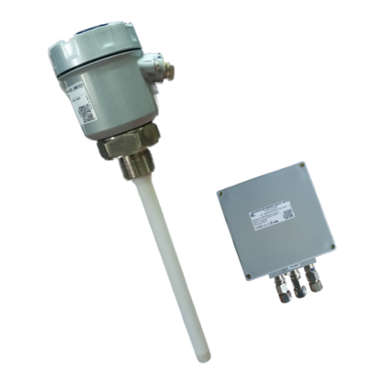
18 Product Selection Order Code ..........® Sapcon Instruments Pvt.Ltd. - Page 3 List of Figures SLC Product Image ..........
-
Page 4: Revision History
• Copyright: All content on this document, such as text, graphics, logos and images is the property of Sapcon Instruments Pvt. Ltd. The selection, arrangement and presentation of all materials on this document and the overall design of this document is the exclusive property of Sapcon Instruments Pvt. -
Page 5: Introduction
User Manual & Datasheet V 2.2 1 Introduction 3 Features SLC is a capacitance based level limit switch which offer • Power Supply: 90 to 265 V AC & 24 V DC. level detection solution for fine, coarse, bulky solids, non- sticky slurries and liquids. -
Page 6: Electrical Specifications
- Screwed : 1/2", 3/4", 1”, 1 1/2” , 1 1/4” BSP/NPT - Flanged : As per your specifications Standoff Material GI (Galvanized Iron) / Stainless Steel Probe Length 100mm to 20m (Rope arrangement) Table 2: Mechanical Specifications ® Sapcon Instruments Pvt.Ltd. -
Page 7: Application Specifications
Sensing part Stainless Steel/ Mild Steel (plated) Grounding pipe Galvanized steel/ Stainless Steel/Mild Steel (plated) Stand-off Galvanized steel/Stainless Steel/Aluminium Fin Discharge device In case of static charge build-up (for solid application) Table 4: Teflon Coat Probe ® Sapcon Instruments Pvt.Ltd. -
Page 8: Evaluation Unit
Adjustable from 5 to 20 seconds (covered and uncov- ered) applicable for model SLsC-322M and 622M Inter-Connection Between Probe and Evaluation unit, by special coaxial cable with drain wire Weight 2.25 Kgs Over all dimensions As per approved Drawings Table 5: Evaluation Unit ® Sapcon Instruments Pvt.Ltd. -
Page 9: Installation Guidelines
• shield should be fitted above the instrument especially Weatherproofness of enclosure is guaranteed only, if if the operating temperature lies between C and the cover is in place & cable glands adequately tight- ened. ® Sapcon Instruments Pvt.Ltd. -
Page 10: Fail-Safe Mode
• As the SLC is specifically designed to detect point levels in Again rotate the same multiturn set pt. adj. pot 3 slowly the same tank, the range selection is made common to all counter clockwise until the red LED (Alarm 3) just goes the point levels. -
Page 11: The Blind Calibration
Thank you for going through the instructions given in this manual. To further ease the process of installation and use, we have developed special demo videos which are hosted on YouTube. Sapcon’s YouTube channel, SAPCON INSTRUMENTS, lists all these videos: https://goo.gl/dnxfcz Should you require further information regarding installation, use or working of the instrument, please don’t hesitate to contact us. - Page 12 User Manual & Datasheet V 2.2 In an attempt to serve you better, we are open seven days a week (9:30am to 7:30pm). We are available at: • www.sapconinstruments.com • sales@sapcon.in • +91-731-4757575 ® Sapcon Instruments Pvt.Ltd.
-
Page 13: Product Selection Order Code
18 Product Selection Order Code Product SLC_S : SLC Series-Capacitance Type Level Limit Switch SLC_T : SLC Tri_Point-Capacitance Type Level Limit Switch (SL) Type I : Integral (sensor in the same unit) SL : Split (Sensor on the probe, Evaluation Unit on wall mount connected via cable) Housing (Depends on Product &... - Page 14 FA20S6 : 2” ANSI/ASME B16.5 150 Lbs Flange, SS 316 ½ F25MS : 10 mm thick Flange conforming to 2 ” ANSI/ASME B16.5 Flange, MS Plated ½ F25S4 : 10 mm thick Flange conforming to 2 ” ANSI/ASME B16.5 Flange, SS 304 ® Sapcon Instruments Pvt.Ltd.
- Page 15 8T : Up to 80 ° 10T : Up to 100 ° 25T : Up to 250 ° 35T : Up to 350 Standoff Material (8T, 10T) STGI : GI (Galvanized Iron) STS4 : SS 304 STS6 : SS 316 ® Sapcon Instruments Pvt.Ltd.
- Page 16 & 1/2” Thread) 2H30H : 200 to 3000 mm (Grounding) 5H100H : 500 to 10000 mm (ø4mm Rope) 10H200H : 1000 to 20000 mm (ø8mm Rope) SLC_S-I-RB-PCB5S-630-U-RDP-MB5S6-F-SS4-10T-1H15H Example - Shows First Priority Entity Applicable Not Applicable ® Sapcon Instruments Pvt.Ltd.
Need help?
Do you have a question about the SLC and is the answer not in the manual?
Questions and answers