Table of Contents
Advertisement
Quick Links
Advertisement
Table of Contents

Related Manuals for Francis Searchlights VM500RC


Summary of Contents for Francis Searchlights VM500RC
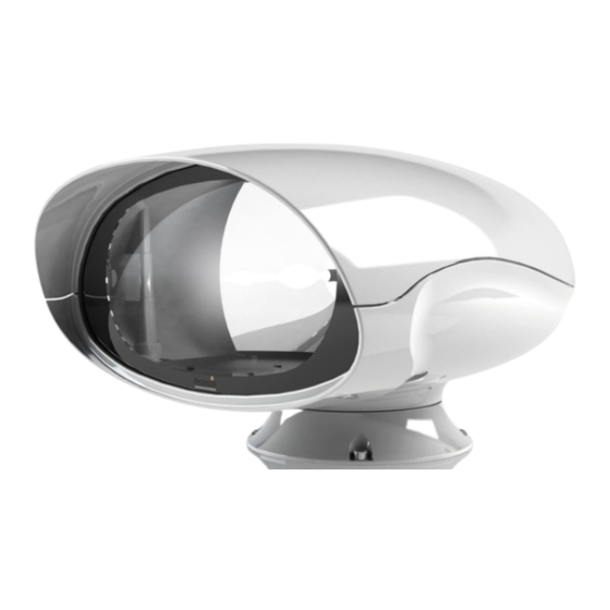
- Page 1 VM500RC 350W Emarc Remote Control Searchlight User / Installation Manual Product Part Number: A7182 – VM500RC 110/240V 350w Emarc Variable Speed Remote Control Searchlight PLEASE NOTE! www.francis.co.uk Please read this manual before installation. C27394 Issue 16 10.11.23 EC1983...
-
Page 2: Table Of Contents
Fault Finding 7.1. Problems After Installation 7.2. Obtaining Fault Status Maintenance and Servicing Wiring Diagram & General Assembly Spare Parts List General Information: Francis Searchlights Ltd Union Road, Bolton, BL2 2HJ United Kingdom T: 00 44 (0)1204 558 960 Sales@francis.co.uk www.francis.co.uk... -
Page 3: Introduction
For your future reference please keep this manual in a safe place. Thank you for specifying a product from the Francis Searchlights range. All Francis products are designed to give complete customer satisfaction and are manufactured to the highest engineering standards to ensure optimum performance and service life. -
Page 4: Safety Precautions
2 – Safety Precautions The following instructions must be adhered to, to ensure a safe working environment and the safety of the user. Note: When unpacking or manoeuvring the searchlight into its fixing position, suitable lifting points must be used to prevent damage to the equipment or personal injury. •... -
Page 5: Technical Information
3 – Technical Information Electrical Input voltage: 110VAC 240 VAC Input current: 3A MAX 1.5A Max PSU output voltage: 50v DC Max PSU current: 7.5A Max Wattage: 350w Dimensions Searchlight Height: 340mm Width: 500mm Depth: 533mm Weight: 17Kgs Height: 430mm Width: 278mm Depth:... -
Page 6: Unpacking And Installation Instructions
4 – Unpacking and Installation Instructions The following instructions should be read and fully understood prior to installing the equipment to ensure that the correct procedures are followed, and all safety precautions are observed. Note: If the equipment has been in storage for a considerable amount of time, it is advisable to conduct a routine maintenance check on all parts before installation. -
Page 7: Electrical Installation
5 – Electrical Installation For safety purposes, only competent personnel should perform the electrical installation. All equipment should be installed to current Electrical Regulations and Standards. Referring to wiring diagram C27386 (at the back of the manual), a supply is fed to the junction box, which then provides a common feed to the searchlight and joystick control panel. - Page 8 To obtain the maximum light output from the searchlight, it is essential that the full operating voltage of the lamp fitted be applied to the lamp holder contacts. Method of Electrical Connection • Disconnect the supply before working on the electrical system. •...
-
Page 9: Start-Up And Operating
6 – Start-up and Operating When fitting the lamp • Always isolate the equipment from the supply when inserting a lamp. • Eye protection must be worn when handling lamps that have been removed from their packaging materials. The protective jacket should not be removed from the lamp for safety reasons, as there is a remote possibility of the lamp shattering violently, especially if it is subjected to mechanical shock or vibration. - Page 10 Before fitting the lamp: • Loosen and remove five M8 socket bolts with the sealing washers on the underneath of the searchlight, then remove the upper hood off the searchlight & store along with the bolts and washers in a safe area. To fit the Emarc lamp •...
- Page 11 Testing Upon correct installation and connection to an electrical supply, the equipment can be tested to ensure its’ correct performance. A competent person with some knowledge of electrical equipment must carry out this work. Equipment required: multi-meter with leads & Ammeter. Using the equation P=VI, the approximate power output of the equipment can be calculated in the following way: •...
- Page 12 Start-Up When the main power is first applied to the searchlight, the searchlight will carry out a self-test, it will Pan to the left limit and the reflector will Tilt down to the limit, once this is complete, the searchlight will then move to the centre position, during this please do not try and operate the searchlight while this test is being carried out.
- Page 13 Set Motion Limit (only available when Remote Focus is fitted) The lamp travel can be limited in all directions. To set a new limit switch the panel on and move the lamp to the desired limit position. Switch the panel off then press and hold the focus button whilst moving the joystick full travel in the direction of the desired limit.
-
Page 14: Fbus Data & Panel Addresses
6.1 - FBUS Data & Panel Addresses The Francis bus (FBUS) is a custom communication protocol based on RS485 two wire bi- directional communication hardware. The system provides a simple bi-directional link between searchlights and joystick panels. The system allows given panels to communicate with different searchlights and allows several panels to communicate with the same searchlight. - Page 15 Standard Joystick Panel – Control (Panel) Address Control Switch Panel EXAMPLES Standard joystick panel – panel address set to 5 Switch 1 = Off Switch 2 = On (Value 4 added to address) Switch 3 = Off Switch 4 = On (Value 1 added to address) 4 + 1 = 5 Speed control card - lamp address set to 11 Switch 6 = Off...
- Page 16 Multiple Searchlights, Joystick Panels and Master Joystick Panel.
-
Page 17: Fault Finding
7 – Fault Finding 7.1 Problems at Installation • If the searchlight completes the Self-Test, e.g., Pan left, Tilts down then returns to centre and the LEDs on the joystick panel are not illuminate, then please check the 4 data cables connections on the FBUS connector located on the back of the control panel assembly, as these data cables could be swapped around, you can check the voltages on the 4 connections, you should get as shown below:... - Page 18 Failure of Emarc Lamp to light Please refer to the following table for the troubleshooting of Emarc lamps. Fault Cause Remedy Anode (large electrode) must Lamp incorrectly fitted always be on top in vertical burning position Wrong Polarity Check polarity, transpose Faulty wiring connections if necessary Check terminals, tighten or...
- Page 19 3. Before a Emarc lamp will ignite, the electrically insulated gas between the electrodes must be ionised. This is done by the ignitor which produces a high frequency voltage (up to 15,000 volts or higher). The ignitor is activated by switching the lamp on and a crackling or hissing noise should be heard.
-
Page 20: Problems After Installation
7.3 Obtaining Fault Status below, to confirm the fault. Once you have confirmed the fault via the joystick panel, please contact Francis Searchlights for ordering the required parts, sales@francis.co.uk If the joystick panel is not communicating with the searchlight and none of the LED’s on the... -
Page 21: Obtaining Fault Status
7.3 - Obtaining Fault Status Fault codes can be accessed, with the joystick panel switched off, press the PANEL button and keeping the PANEL button pressed for 10 seconds. Fault codes are indicated by the PANEL button flashing several times related to the fault. Fault codes are detailed below. If more than one fault is present the PANEL button will indicate them in sequence. -
Page 22: Maintenance And Servicing
8 - Maintenance and Servicing To prolong the service life and performance of your searchlight, the following maintenance guidelines are recommended: • Maintenance checks should be conducted before every voyage or at least every three months. • Before checking, disconnect the equipment from the supply. •... -
Page 23: Wiring Diagram & General Assembly
9 - Wiring Diagram & General Assembly Drawing No: Description A7182 VM500RC 350W General Assembly C27386 Wiring Diagram C27312 Joystick Panel Assembly C27381 Junction Box Assembly... - Page 28 Searchlight Item Part Quantity Number Number Description D27734 350w Emarc Lamp C26139-00 Front Glass C26184-00 Front Glass Gasket C26183-00 Sealing Strip Gasket C26475-00 Base Gasket Base ‘O’ Ring C23808-00 C28025-01 Focus Motor Assembly C23802-00 Reflector C26843-00 Pulley Belt...
- Page 29 Searchlight Item Part Quantity Number Number Description C24181-00 Igniter C28654-01 Tilt Motor Assembly C29521-01 Pan Motor Assembly C27288-00 Heater C29536-01 Speed Controller PCB C27650-00 Tilt Microswitch C25022-00 Proximity Switch...
-
Page 30: Spare Parts List
Searchlights spare parts. This will ensure that any warranties on your equipment will not be invalidated. When ordering spare parts please contact the Sales Department at Francis Searchlights Limited sales@francis.co.uk . Please always quote searchlight model and serial number, which you can...
Need help?
Do you have a question about the VM500RC and is the answer not in the manual?
Questions and answers