Table of Contents
Advertisement
Quick Links
OPERATOR'S MANUAL
SINGLE OUTPUT, UNIVERSAL INPUT
SINGLE PHASE, 0.99 POWER FACTOR
KEPCO INC.
An ISO 9001 Company.
IMPORTANT NOTES:
1)
The contents of this manual are protected by copyright. Reproduction of any part can be
made only with the specific written permission of Kepco, Inc.
2)
Data subject to change without notice.
©2010, KEPCO, INC
P/N 228-1498-R5
KEPCO, INC. 131-38 SANFORD AVENUE FLUSHING, NY. 11355 U.S.A. TEL (718) 461-7000 FAX (718) 767-1102
RKW 300W SERIES
POWER SUPPLY
MODEL
RKW 300W SERIES
POWER SUPPLY MODELS
RKW 3.3-70K, RKW 5-60K, RKW 12-27K,
RKW 15-22K, RKW 24-14K, RKW 28-12K,
RKW 48-7K
email: hq@kepcopower.com World Wide Web: www.kepcopower.com
KEPCO
THE POWER SUPPLIER™
®
Advertisement
Table of Contents

Subscribe to Our Youtube Channel
Related Manuals for KEPCO RKW 300W Series


Summary of Contents for KEPCO RKW 300W Series
- Page 1 Data subject to change without notice. KEPCO ® ©2010, KEPCO, INC THE POWER SUPPLIER™ P/N 228-1498-R5 KEPCO, INC. 131-38 SANFORD AVENUE FLUSHING, NY. 11355 U.S.A. TEL (718) 461-7000 FAX (718) 767-1102 email: hq@kepcopower.com World Wide Web: www.kepcopower.com...
-
Page 2: Table Of Contents
TABLE OF CONTENTS SECTION PAGE 1. Introduction................................ 1 Scope of Manual............................. 1 Description..............................1 2. Specifications ..............................1 3. Operation................................5 Voltage Adjustment ............................6 Remote Voltage Control ..........................7 Remote Turn On-Turn Off..........................7 4. Alarm Functions..............................8 Overvoltage and Overtemperature Protection ....................8 Overcurrent Protection ........................... -
Page 3: Introduction
(input voltage range 85 to 265 Va-c), 50-60 Hz (input frequency range 47-66Hz). They will also operate on 110V to 370V d-c input. The RKW 300W Series employs a light weight ferrite core with 200 KHz switching frequency. Regulation is provided by pulse width modulation. A power stage with a MOSFET on each side of the primary winding, operating in the forward mode provides a smooth isolated d-c output. -
Page 4: Power Supply Ratings And Specifications
TABLE 2. POWER SUPPLY RATINGS AND SPECIFICATIONS SPECIFICATION DESCRIPTION Input Voltage 85-265V a-c (0 to 100% load, -10 to 65°C) 110-370V d-c Polarity insensitive (0 to 100% load, -10 to 65°C) Safety agency approval applies only to a-c input operation. Input Source Frequency 50 to 60 Hz 47-440 Hz. - Page 5 TABLE 2. POWER SUPPLY RATINGS AND SPECIFICATIONS (CONTINUED) SPECIFICATION DESCRIPTION Remote Control ON/OFF: "High", 2.4V to 24V (or open), unit OFF- Fan Off ; "Low", 0.0V to 0.4V (or closed), unit ON. Source current is 1.6mA maximum at low level, and sink current is 1.0 mA maximum at high level.
-
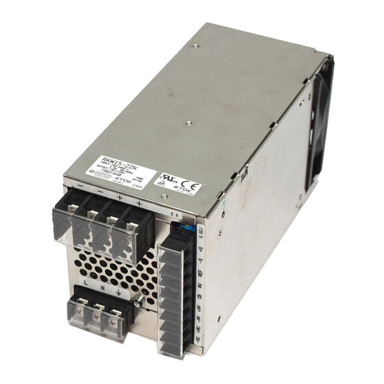
Page 6: Mechanical Outline Drawing Of The Rkw 300W Power Supply
RKW 300W 060110... -
Page 7: Operation
The power supply will startup from -20 to -10 °C but may not meet the specifications FIGURE 2. POWER RATING VS. TEMPERATURE Maintain a 1.25 in. (30 mm) min. distance between ventilation holes, fan surface and surrounding equipment and install to provide heat-outside air exchange FIGURE 3. -
Page 8: Voltage Adjustment
NOTE Unit is shipped with shorting links (not shown) connecting +RC to –RC (see PAR. 3.3) and REF to RV (see PAR. 3.2) and with local sensing cables installed (connects +DC Output to +S and –DC Output to –S) (see PAR. 5.2) FIGURE 4. -
Page 9: Remote Voltage Control
Sense terminals with a precision voltmeter and turn the voltage control to the desired operating value. Refer to Table 1 for the recommended Adjustment Range of all the RKW 300W Models REMOTE VOLTAGE CONTROL The unit is shipped with a shorting link in place between RV and REF terminals. Removal of this link allows the output voltage to be adjusted by either a trimmer pot (resistance) or by an external variable voltage source across the RV terminal and –S terminal. -
Page 10: Alarm Functions
terminals are shorted, the output returns to within specifications. At low level logic, the maximum source current is 1.6mA and at high level the sink current is 1.0mA. The RC terminals must remain shorted if remote ON-OFF is not used. The RC terminals are isolated from both the AC input and DC output terminals. -
Page 11: Undervoltage
FIGURE 7. RKW 300W POWER FAILURE TIMING DIAGRAM UNDERVOLTAGE If the output voltage of the power supply falls below 80 percent of the programmed voltage the power failure alarm will go to the high logic state. LOAD CONNECTION CONNECTING THE LOAD USING LOCAL SENSING To connect the load for local sensing, connect the +S to (+) terminal and –S to (–) terminal. -
Page 12: 5.3.1 Current Balancing
5.3.1 CURRENT BALANCING Current balancing (equalization) conditions required for up to four RKW 300W units in parallel are: 1. Output current of each power supply should be within 20 to 90% of the total output current rating. 2. The output voltage of any Power Supply individually must be within 2% maximum of the other power supply output voltage setting. -
Page 13: 5.3.2 Master-Slave Configurations
5.3.2 MASTER-SLAVE CONFIGURATIONS Master-slave operation allows the output voltage of all the power supplies connected in parallel to be adjusted at the same time by using the Vadj control on the designated master power supply. 5.3.2.1 MASTER-SLAVE, MULTIPLE LOADS Figure 10 shows the master-slave connection of three power supplies in parallel, each having an independent load, with output voltage controlled by the Vadj control of the master power supply. -
Page 14: Preliminary Electrical Check
FIGURE 12. SERIES CONNECTION PRELIMINARY ELECTRICAL CHECK Connect an adjustable load across the power supply output terminals, on the top side of the front panel (see Figure 4). The load must have a dissipation rating of at least 600 Watts. Connect a voltmeter and an oscilloscope across the power supply output terminals (should be linked to the respective sensing terminals, +S and –S). - Page 15 You must register your product to comply with the terms of the warranty. Either fill out the form below and mail or fax to Kepco, or for rapid on-line registration go to: http://www.kepcopower.com/warranty.htm PRODUCT PURCHASED: REGISTER TO: Model Number)______________________________________ Registered by:________________________________________...
- Page 16 FOLD HERE Please place stamp here KEPCO, INC. 131-38 SANFORD AVE. FLUSHING, NY 11355 USA CUT HERE...
Need help?
Do you have a question about the RKW 300W Series and is the answer not in the manual?
Questions and answers