Table of Contents
Advertisement
Quick Links
Advertisement
Table of Contents

Related Manuals for inVENTer Pure


Summary of Contents for inVENTer Pure
- Page 1 Installation instructions Pure control unit www.inventer.de...
- Page 2 The illustrations in this document may differ slightly from the design of the product that you have purchased. The same functionality is ensured despite any design deviations. This documentation is updated regularly. Necessary corrections and appropriate supplements are always included in subsequent editions. You can also find the latest version at www.inventer.eu/ downloads. Company information...
-
Page 3: Table Of Contents
TABLE OF CONTENTS Table of contents User and safety instructions ....................4 User information ......................4 Safety instructions ......................5 System overview: Pure controller ..................7 Construction ........................8 Function ......................... 8 Electrical connection ......................10 Connections ........................10 Cabling ........................... 11 Preparing for installation ...................... -
Page 4: User And Safety Instructions
USER AND SAFETY INSTRUCTIONS User and safety instructions Thank you for purchasing this high quality product from inVENTer! This section provides an overview of the basic safety precautions for safe and proper operation of your control unit. User information Safety and warning instructions The safety and warning instructions in these installation instructions have a uniform structure and are marked with a symbol on the left side of the instruction. -
Page 5: Safety Instructions
USER AND SAFETY INSTRUCTIONS Safety instructions The installation instructions are part of your Pure control and must be available at all times (see www.inventer.de/downloads). When handing the system to a third party, the information regarding access to the installation instructions must be handed over also. - Page 6 Any kind of use other than the intended use will exclude all liability claims. Improper use The Pure controller is intended exclusively for the control of the ventilation units specified in the section on intended use. Any other use is strictly prohibited.
-
Page 7: System Overview: Pure Controller
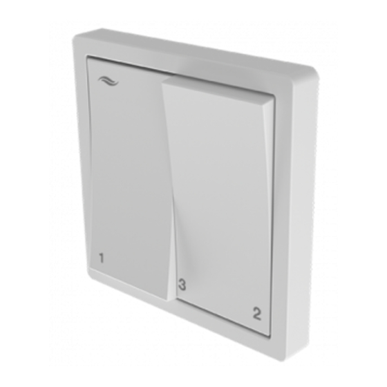
Integrated indicator lights mean that the switch acts simultaneously as a visual feedback / display for the user. The Pure controller can be used either as a base control unit or with additional sensors connected. When used as a base control unit, there is a choice of operating modes for the ventilation unit and the air flow can be set at 3 predefined levels. -
Page 8: Construction
Pure controller without connected sensor technology If no sensor is connected, the operating mode and intensity of the air flow can be set on the Pure controller. The heat recovery and ventilation operating modes can be changed by moving the left-hand rocker switch back and forth 2 times. - Page 9 SYSTEM OVERVIEW: PURE CONTROLLER Pure controller with connected sensor technology If sensors are connected to the Pure controller, the range of the controller's functions increases and this also allows demand-based ventilation alongside manual ventilation. The sensor used must have a potential-free relay contact as its output.
-
Page 10: Electrical Connection
Direction signal 2 Brown Connecting ter- Switching contact 1 – External interface minal, 2-pole (optional) Switching contact 2 – Screw terminal Rocker switch 1 Black Connecting White cable, Switch connection Rocker switch 2 Black 4-wire Brown Pure controller | Installation instructions... -
Page 11: Cabling
V DIR2 sensor Kontakt NC Pure p4 Fire Pure p4 Fire Flat sensor Figure 2: Pure controller - connection example Components A Status LEDs D Sensor technology (optional) B Series switch programming unit E Switching power supply unit C Pure control module F Terminal blocks, 5-pole ... -
Page 12: Preparing For Installation
- in rooms which are free from aggressive or corrosive gases and extreme dust exposure. • The Pure controller is installed on the interior wall via a mounting box. Recommended installation height: 1.05 m floor to lintel height (reachability for operation) -
Page 13: Installation Dimensions
2x 82 al-chamber box Wall opening for flexible flush-mounted plasterboard box Switching power supply unit (Switching PSU) Control cabinet switching PSU 25 (1.5 HP) – Flush-mounted switching PSU Table 1: Installation accessories and installation dimensions Pure controller | Installation instructions... -
Page 14: Installation
- Signal cable, 2-wire, between the controller installation site and installation site of the external sensor ► Route the cables at the controller installation site into the mounting box. ► Install the mounting box on the interior wall. Pure controller | Installation instructions... -
Page 15: Connecting The Switching Power Supply Unit (Psu)
• Connect the neutral conductor (blue) to wire N. ► Place the power supply unit in the lower cavity / pocket of the mounting box. The switching power supply unit output wires extend into the interior. The flush-mounted switching PSU is connected. Pure controller | Installation instructions... -
Page 16: Distributing Fan Cables
INSTALLATION Distributing fan cables We recommend the star-shaped connection of fans to the Pure controller. The distribution of wires to the fan in this case takes place within the prepared mounting box using 5-pole terminal blocks. Alternatively, the fans can be connected in sequence. In this case, no distribution takes place. The fan BUS is attached directly to the terminal on the control module. -
Page 17: Connecting The Control Module
INSTALLATION Connecting the control module The control module contains the electronics for controlling the inVENTer ventilation units with heat recovery, as well as an LED assembly that acts as visual feedback for the user. The control module is positioned in the mounting box after connection. - Page 18 • Red LED (red/yellow wires) in the lower area of the left-hand rocker switch. • Green LED (green/yellow wires) in the lower area of the right-hand rocker switch. You have installed the Pure controller. Pure controller | Installation instructions...
-
Page 19: Technical Data
External switching contact (optional) Safety device Potential-free break contact Other sensor technology Potential-free make contact Operating temperature [°C] 5 ... 50 Electrical protection area Outside protection areas 0 ... 2 (in accordance with VDE 0100) Conformity Pure controller | Installation instructions... -
Page 20: Scope Of Supply
Pure p4 Fire controller incl. DIN rail switching PSU 1003-0146 Pure p4 Fire Flat controller incl. flush-mounted switching PSU 1003-0147 Pure p4 Fire Flat controller incl. DIN rail switching PSU 1003-0148 Accessories and spare parts Contact your local distributor to order accessories for your ventilation system. -
Page 21: Troubleshooting
(Flat): Sensor Fans at output level 75 %. p4 Fire (Flat): Pressure monitor If you cannot eliminate the fault, please contact our technical customer service. You can find information about doing so in section 11: Service. Pure controller | Installation instructions... -
Page 22: Guarantee And Warranty
The guarantee covers all defects that were present at the time of purchase. Failure to observe the intended use will invalidate all warranty claims. Manufacturer warranty inVENTer GmbH provides a five-year warranty for electronic components. This covers premature product wear. Further information about the warranty is available at www.inventer.de/guarantee... - Page 23 GUARANTEE AND WARRANTY NOTES Pure controller | Installation instructions...
- Page 24 GmbH Ortsstraße 4a 07751 Löberschütz Germany www.inventer.eu Subject to modifications. We accept no liability for printing errors. Item number: 5021-0024 Version: 1.0 – 02/2022...
Need help?
Do you have a question about the Pure and is the answer not in the manual?
Questions and answers