Table of Contents
Advertisement
Quick Links
Installation and Maintenance
Instruction Manual
SILVER SERIES TRANSMITTERS
In the following configuration:
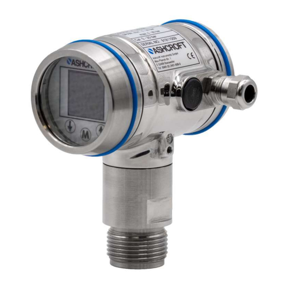
PS55 Process pressure and level transmitter SILVER SERIES
CS55 Cleanline pressure and level transmitter SILVER SERIES
PS55
CS55
IM PS55-CS55(SILVER SERIES) 4-20 mA+HART EN Rev A
09/2019
Page 1 of 18
P/N 095I508-02EN
Advertisement
Table of Contents

Subscribe to Our Youtube Channel
Related Manuals for Ashcroft SILVER Series


Summary of Contents for Ashcroft SILVER Series
- Page 1 Installation and Maintenance Instruction Manual SILVER SERIES TRANSMITTERS In the following configuration: PS55 Process pressure and level transmitter SILVER SERIES CS55 Cleanline pressure and level transmitter SILVER SERIES PS55 CS55 IM PS55-CS55(SILVER SERIES) 4-20 mA+HART EN Rev A...
-
Page 2: Table Of Contents
Storage ................................9 Assembly/Installation ..............................10 Installing Weld-On Nipple ..........................10 Installing Process Transmitter SILVER SERIES PS55 (with weld-on nipple) ........... 10 Installing Cleanline Transmitter SILVER SERIES CS55 (with weld-on nipple) ..........10 Mounting Position .............................. 10 Mounting Position Effect............................ 10 Calibration ................................. - Page 3 16.1 Safety ................................17 16.2 Removal ................................. 17 16.3 Disposal ................................. 17 Appendix ................................17 17.1 Data sheet for SILVER SERIES PS55 and CS55 ..................17 17.2 Declaration of conformity model PS55 and CS55 ..................18 Page 3 of 18...
-
Page 4: General Remarks
Check if the specifications of the transmitter meet the needs of the process conditions When the SILVER SERIES PS55 or CS55 is used as a level transmitter, be aware of the place where the transmitter is mounted. Here are some suggestions: 1. -
Page 5: Manufacturer's Address, Customer Services
The devices are only to be used for the intended purpose as described by the manufacturer. The SILVER SERIES transmitters are solid-state pressure- and level transmitters based upon a piezoresistive silicon sensor, with a very high burst pressure. Pressure of the medium applied on a sensor element, creates a very small deflection of the silicon substrate and bridge network. -
Page 6: Signs/Safety Markings
3.1 CE / EMC – Rules All SILVER SERIES transmitters are manufactured in accordance with the RFI / EMC directives and comply with the CE standard. All transmitters are fitted with RFI filters, which provide optimum, trouble-free operation. Our products are in conformity with EMC-Directive 2014/30/EU based on test results using harmonized standards. -
Page 7: External Load
6 Construction and function The SILVER SERIES transmitters are are solid-state pressure- and level transmitters based upon a piezoresistive silicon sensor, with a very high burst pressure. The sensor element is mounted in a stainless steel foot. Inside the foot also a temperature sensor is mounted to ensure the process temperature. -
Page 8: Process Transmitter Silver Series Ps55
6.2 Cleanline transmitter SILVER SERIES CS55 The SILVER SERIES CS55 are specially designed with a flush mounted diaphragm so they fully meet the needs of the food, pharma and chemical industries. Standard the wetted parts are made of St.St. 316 L, other materials are available, like Hastelloy C. -
Page 9: Barometric Reference
Front view: Digital local indication with transparent cover, option: DG (extra price) Material Description Material Description St.St. 316 ① Cover St.St. 304 ⑦ Foot St.St. 304 ② Display with push buttons ⑧ Lock Ring St.St. 316 L ③ O-Ring EPDM ⑨... -
Page 10: Assembly/Installation
Prepare the hole by bevelling the edge to accept filler material. Remove the weld-on nipple from the transmitter. Remove the PTFE packing of the Cleanline transmitter SILVER SERIES CS55 Remove the gasket and O-ring out of the weld-on nipple! Improper installation may result in distortion of the weld-on nipple. -
Page 11: Calibration
transmitter the zero must be set to 4,00 mA with P103 (cancel mounting position effect see Section 12.3 ). This will not affect the span. 8.6 Calibration All transmitters are fully calibrated at the factory, to customer specified range. If calibration is not specified, the transmitter will be calibrated at the maximum span. -
Page 12: Functions Of Push Buttons
10 Functions of Push Buttons The SILVER SERIES transmitter has a high contrast display for optimal readout. The menu is controlled by 3 pushbuttons. Navigate with the up and down through menus and measuring values. Enter a menu and confirm selections with the menu button. -
Page 13: P102 Span Adjustment
5. The transmitter will return to the home screen. The measurement value at atmospheric pressure is now -100 mBar. At an applied pressure of 100 mbar the transmitter will display 0 mbar. The transmitter can be adjusted to zero in a real process situation. The transmitter will measure the pressure in an actual process. -
Page 14: P105 Output Selection
12.5 P105 Output Selection Factory setting = 4 - 20 mA 1. Navigate to program point P105, and push the menu button to enter the menu. 2. Two choices appear on the screen: 4-20 and 20-4 3. Make an output choice and push the menu button to confirm. The transmitter will return to the home screen. -
Page 15: P110 Burst Mode (Hart®)
17 Vdc must be used. 13.1 Programming with the hand held terminal The SILVER SERIES can be easily programmed with the Hand Held Terminal (HHT) from the "HART Foundation" (type 275 or 375 Hart Communicator). Page 15 of 18... -
Page 16: Servicing
® Option 1: HART Handheld terminal connected across the transmitter. Power 17 – 36 Vdc Supply 250 Ω ® Option 2: HART Handheld terminal connected across the loop resistor. Power 17 – 36 Vdc Supply 250 Ω 14 Servicing The device is maintenance-free. However, to ensure reliable operation and a long lifetime for the device, we recommend that it is checked regularly 14.1 Safety When undertaking servicing work on the device, the pressure lines must be depressurized, the electrical connections... -
Page 17: Conduct In The Event Of Faults
Please help to protect the environment and dispose of or recycle the devices and components used in accordance with the applicable regulations. 17 Appendix 17.1 Data sheet for SILVER SERIES PS55 and CS55 Detailed data sheet is available from supplier’s website (see 1.7 Manufacturer’s address, customer services) This Table refers to specific documents:... -
Page 18: Declaration Of Conformity Model Ps55 And Cs55
17.2 Declaration of conformity model PS55 and CS55 Page 18 of 18...
Need help?
Do you have a question about the SILVER Series and is the answer not in the manual?
Questions and answers