Table of Contents
Advertisement
Quick Links
Installation and Maintenance
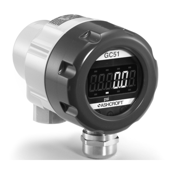
Instructions for GC51 Rangeable
Pressure Transmitter
LOOK FOR THIS
AGENCY MARK ON
OUR PRODUCTS
© 2011 Ashcroft Inc. 250 East Main Street, Stratford, CT 06614 USA
Tel: 203-378-8281, Fax: 203-385-0402 www.ashcroft.com
All sales subject to standard terms and conditions of sale.
I&M011-10159_Rev. C_6.03_GC51
Version 6.03 5/11
Advertisement
Table of Contents

Subscribe to Our Youtube Channel
Related Manuals for Ashcroft GC51


Summary of Contents for Ashcroft GC51
- Page 1 LOOK FOR THIS AGENCY MARK ON OUR PRODUCTS Version 6.03 5/11 © 2011 Ashcroft Inc. 250 East Main Street, Stratford, CT 06614 USA Tel: 203-378-8281, Fax: 203-385-0402 www.ashcroft.com All sales subject to standard terms and conditions of sale. I&M011-10159_Rev. C_6.03_GC51...
-
Page 3: Table Of Contents
CONTENTS CAUTION .................... 1. PREFACE .................... 2. OVERVIEW ..................3. FEATURES ..................4. SPECIFICATION..................5. MOUNTING..................5.1 Mounting Location ..............5.2 Mounting Options ..............5.3 Pressure Connection ..............6. DIMENSIONS ..................10 7. WIRING ....................10 7.1 Cable / Wiring Specifications ............10 7.2 Wiring Instructions .............. -
Page 5: Caution
A failure resulting in injury or damage may be caused by excessive overpressure, excessive vibration or pressure pulsation, excessive instru- ment temperature, corrosion of the pressure containing parts, or other misuse. Consult Ashcroft Inc., Stratford, Connecticut, USA before in- stalling if there are any questions or concerns. 2. OVERPRESSURE:... -
Page 6: Preface
Refer to Ashcroft Bulletin GC-51 for product specifications and appli- cable operating conditions. OVERVIEW The GC51 is a 4-20ma loop powered (two-wire)pressure transmitter with dis- play incorporating Ashcroft’s polysilicon thin film sensing element which pro- vides high cycle life, excellent overpressure ratings, high stability and durability. -
Page 7: Specification
SPECIFICATION Item: Description A. Media / Wetted Parts: Fluids or gases compatible with 316SS and 17-4PH SS B. Overpressure (Proof): –1500 psi FS and below; 200% FS value –3000, 5000 psi; 150% FS value –7500 psi; 120% FS value C. Supply Voltage: 12-32 Vdc D. -
Page 8: Mounting
L. Pressure Connection: ⁄ NPT Female M. Enclosure: Material: Aluminum (die cast) Environmental Rating: IP65 / NEMA 4X N. Mounting: Pressure Port Location: Lower (bottom) Panel mounting: via bracket included Location: compliant with environmental ratings and where display does not get directs sunlight O. -
Page 9: Mounting Options
5.2. Mounting Options Direct connection to pressure ports with suitable piping and / or pres- sure fitting or with bracket included for panel mounting. If using cable it is recommended that the cable exit downward. 5.3. Pressure Connection A. Only apply wrench to pressure port flats, DO NOT apply force to the housing. -
Page 10: Wiring
• To reduce potential for noise do not run pressure transmitter cable / wires alongside (same conduit as) high voltage (line power) lines. For optimum results use dedicated conduit for GC51 cable / wires. • If using the Cable Gland termination option must use cable within pre- viously noted diameters to maintain environmental ratings. - Page 11 • Wiring stripping instructions, remove cable jacket 2-3˝ and strip wires 0.25˝. Shield / drain wire should not be exposed at the pressure transmitter termination. • Remove cover and carefully remove the display to access the terminal strip, take care not to mishandle the display and associated electronics.
- Page 12 • If using the Cable Gland be sure to properly tighten sealing grommet be- fore applying any tension on the cable, the cable gland provides strain re- lief and environmental sealing. • Tighten GC51 cover to maintain environmental rating. • Connect to power source and receiver and power on to confirm correct wiring.
- Page 13 Load Limitations 4-20mA Output Only Loop Resistance ( ) 1020 1000 OPERATING REGION LOOP SUPPLY VOLTAGE V min = 12V+[.022A*R L )] *Includes a 10% safety factor R L = R S + R W R L = Loop Resistance (ohms) R S = Sense Resistance (ohms) R W = Wire Resistance (ohms)
-
Page 14: Display Functions
8. DISPLAY FUNCTIONS Test Terminals GC51 Measured Data Pressure Arbitrary Unit Monitor Unit Monitor MODE key DOWN key UP key Function Designation Pressure, linear scaling value, hold value 1. Measured Data Display (max./ min), are displayed. When either indicator is ON, the display is 2. -
Page 15: Mode Changes
MODE CHANGES • Measurement Mode (Section 11 for further detail) will be entered upon power-on. Setting Mode (Section 13 for further detail) is entered by pressing and holding the MODE button for more than 3 seconds. If there is no button operation for 10 minutes in the setting mode, it will shift back to the Measurement Mode automatically. -
Page 16: Measurement Mode
11. MEASUREMENT MODE The measurement mode includes pressure display mode and linear (scaling) display mode. 11.1 Filter (Damping) Set the filter before setting pressure display mode or linear (scal- ing) display mode. The filter is based on the moving average of the pressure data to decrease display “bounce”... - Page 17 Select the filter of “8 times” ⇒ Setting item Select the “Pressure display mode” ⇒ Setting item Set output zero point as “10.0%F.S.” (10 psi) ⇒ Setting item Set output span point as “90.0%F.S.” (90 psi) ⇒ Setting item Setting Example 1: Pressure Display Mode Using a standard pressure range of 0 to 100 psi, the steps to change the display and analog output zero and span points to 10 and 90 psi respectively are as follows: First, set the Filter.
-
Page 18: Linear Display Mode
This mode is used for display/analog output of the scaling value where the pressure is linearly converted to an arbitrary physical quantity (user defined, GC51 is supplied with display unit “PSI”). FURTHER DETAIL regarding menu and button sequence is shown in Section 14.2-14.3. - Page 19 Output zero point (4mA). Setting Example 2 : Linear Display Mode In this example the desire of the user is to use the GC51 as a “load meter” with the arbitrary unit being “ton”. Using a pressure range of 0 to 100psi, Setting Mode to display the OFFSET for minimum pressure 10psi as 0.00, the FULL SCALE for maximum pressure...
- Page 20 For display mode, select “Linear display mode” ⇒ Setting item Set min. pressure P1 as “10 psi” ⇒ Setting item Set max. pressure P2 as “60 psi” ⇒ Setting item Set decimal point position of linear display ⇒ Setting item as “two digit”...
-
Page 21: Min/Max Display
11.4 Minimum / Maximum Display In Pressure Display Mode or Linear Display Mode the maximum and minimum values are captured into nonvolatile memory (EEP- ROM). The following steps describe how to display these values. A. Maximum Value In Measurement Mode (either pressure or linear indication mode), press UP $ button to display the maximum value. -
Page 22: Out Of Range Display
Minimum / Maximum Reset The Minimum / Maximum values can be reset when in either Minimum / Maximum display or Measurement Mode by holding the DOWN # but- ton for more than three seconds, “cLr” will appear on the display for two seconds and the Minimum and Maximum values will be removed. -
Page 23: Zero Adjustment Mode
–5%F.S. or less 105%F.S. or more • Span Over 005. 0 105. 0 ..display 12. ZERO ADJUSTMENT MODE When in Measurement Mode the zero reading can be adjusted. To adjust the zero reading be sure the pressure connection port (or the system to which it is connected) is open to atmosphere and hold the UP $ button for more than 3 seconds. - Page 24 14. SETTING MODE The setting mode includes access to pressure display mode and linear display mode. In addition loop check (section 13.4) can be performed in each mode. 14.1 Setting Items for Pressure Display Mode (Re-scaling in “psi” units) Set the filter before setting the pressure setting mode Note: see page 24 for full menu.
-
Page 25: Setting Items For Linear Display Mode (Re-Scaling In Arbitrary User Defined Units)
14.2 Setting Items for Linear Display Mode (Re-scaling in arbitrary user defined units) Set the filter before setting the linear display mode (Refer to Section 11.1). The following table is the Setting Example 1, Linear Display Mode, Section 11-3. This applies when re-scaling in arbitrary user defined units. Setting Setting Setting... - Page 26 †In the setting of a pressure, the decimal point position is fixed for each pressure range. (Refer to section 10, Power-on Message). The maximum pressure can be set from the value which is more than 25%F.S. of the pressure range above the minimum pressure. The values under 25%F.S. cannot be increased or decreased by $ # key.
-
Page 27: Setting Procedure
14.3 Setting Procedure Note: Holding the button for more than 3 seconds returns to display mode. -
Page 28: Loop Check
14.4 Loop Check In each display mode, regardless of applied pressure, the loop check can be activated by following the push button sequence in Section 13.1 and 13.2. This will link the display with the analog output. This allows for checking wiring, receivers, general trou- bleshooting etc. - Page 29 • Analog output terminal check When the front cover is removed, the analog output check terminals (pad: CH+, CH–) are visible at the upper part of the display sub- strate. The analog output can be checked during measurement mode or loop check by applying a probe such as a tester for current measurement, onto the check terminal of the substrate, as shown in the following figure.
-
Page 30: Maintenance & Service
15. MAINTENANCE & SERVICE • Periodic inspection Depending upon the type of use periodic inspection is recommended at least once a year. Please refer to the following items for periodic inspection: 1. Appearance 2. Display/output check via appropriate pressure standard. 3. - Page 32 © 2011 Ashcroft Inc. 250 East Main Street, Stratford, CT 06614 USA Tel: 203-378-8281, Fax: 203-385-0402 www.ashcroft.com All sales subject to standard terms and conditions of sale. I&M011-10159_Rev. C_6.03_GC51...
Need help?
Do you have a question about the GC51 and is the answer not in the manual?
Questions and answers