Table of Contents
Advertisement
Quick Links
Installation and Maintenance
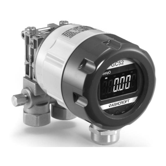
Instructions for GC52
Differential Pressure
Transmitter
LOOK FOR THIS
AGENCY MARK ON
OUR PRODUCTS
© 2007 Ashcroft Inc. 250 East Main Street,
Stratford, CT 06614 USA
Tel: 203-378-8281, Fax: 203-385-0402, www.ashcroft.com
All sales subject to standard terms and conditions of sale.
I&M011-10160 -7/10/08
Version 5.0 10/07
Advertisement
Table of Contents

Related Manuals for Ashcroft GC52


Summary of Contents for Ashcroft GC52
-
Page 1: Installation And Maintenance
LOOK FOR THIS AGENCY MARK ON OUR PRODUCTS Version 5.0 10/07 © 2007 Ashcroft Inc. 250 East Main Street, Stratford, CT 06614 USA Tel: 203-378-8281, Fax: 203-385-0402, www.ashcroft.com All sales subject to standard terms and conditions of sale. I&M011-10160 -7/10/08... -
Page 3: Table Of Contents
CONTENTS CAUTION .................... 4-5 1. PREFACE ..................2. OVERVIEW ..................3. FEATURES ..................4. SPECIFICATIONS................5. MOUNTING ..................5.1 Mounting Location ................ 5.2 Mounting Options ................ 5.3 Pressure Connection..............6. PIPING ....................7. WIRING ....................7.1 Cable / Wiring Specifications............7.2 Wiring Instructions................ -
Page 4: Caution
A failure resulting in injury or damage may be caused by excessive overpressure, excessive vibration or pressure pulsation, excessive in- strument temperature, corrosion of the pressure containing parts, or other misuse. Consult Ashcroft Inc., Stratford, Connecticut, USA before installing if there are any questions or concerns. OVERPRESSURE:... -
Page 5: Preface
USE IN LIFE SUPPORT DEVICES Ashcroft Inc. products are not authorized for use as critical components in life support devices or systems without the express written approval of the Gen- eral Manager, Stratford Operations of Ashcroft Inc. As used herein:... -
Page 6: Specifications
(5)Loop Check Function: Allows the user to output an analog signal cor- responding to differential pressure without applying pressure, simplify- ing system maintenance and troubleshooting. (6)Zero and Span Adjustment: The adjustment of the Zero (4mA) and Span (20mA) reading via internal push buttons. (7)IP65 / NEMA 4X Environmental Rating: Enclosure environmental rat- ing suitable for indoor and outdoor installation, depending upon operat- ing temperature range.*... - Page 7 9. Units Pressure Units: inH O (2), (1) arbitrary Internal key switches (Mode, T, S) 10. Setting Adjustments Scaling function: Linear output Filter function: User adjustable output damping select from 0, 2, 4, 8 and 16 (None, 2, 4, 8, and 16 (s)). Loop check function: User adjustable output for loop/ system check and troubleshooting, 4-20mA.
-
Page 8: Mounting
When loosening the valve do not back off by more than three turns from the closed position. (2) Panel Mounting Similar to (1) above except that the GC52 is put between the man- ifold and the bracket and then the (4) socket head bolts (M4x40) are installed. -
Page 9: Piping
Lower connection diagram Connection: Lower side. M 4 x 4 0 • 1.0 in. (25.4mm) mounting manifold P a n e l m o u n t i n g b r a c k e t 1.4 (35) 1.8 (45.4) .33 (8.5) .55 (14) Equalizing... -
Page 10: Wiring
• To reduce potential for noise do not run pressure transmitter cable / wires alongside (same conduit as) high voltage (line power) lines. For optimum results use dedicated conduit for GC52 cable / wires. • If using the Cable Gland termination option must use cable within previously noted diameters to maintain environmental ratings. - Page 11 Power source + Receiver − + − Transmission cable Terminal box Shield Display (board) Notch CASE Transmission cab (Twist) Inside sensor Line Sheath DISPLAY LCD holder • Turn display over to expose terminal strip, make positive and Power supply terminal block negative connections, Turn with a screwdriver Wire...
- Page 12 • Tighten GC52 cover to maintain environmental rating. • Connect to power source and receiver and power on to confirm cor- rect wiring (see Section 10 for more detail).
-
Page 13: Display Functions
8. DISPLAY FUNCTIONS Test Terminals CH– GC52 Differential pressure unit monitor In H Scaling - Arbitrary unit monitor 8. 8 . 8 . 8 . 8 . 8 . Measured data display ▼ ▲ MODE key UP key DOWN key... -
Page 14: Mode Changes
MODE CHANGES • Measurement Mode (Section 11 for further detail) will be entered upon power-on. Setting Mode (Section 13 for further detail) is entered by pressing and holding the MODE button for more than 3 seconds. If there is no button operation for 10 minutes in the setting mode, it will shift back to the Measurement Mode automatically. -
Page 15: Measurement Mode
11. MEASUREMENT MODE The measurement mode includes differential pressure display mode, and to k linear (scaling) display mode. For the setting items , please refer to the Setting Mode (section13.1). 11.1 Filter Set the filter before setting pressure display mode or linear (scaling) display mode. -
Page 16: Linear Display Mode (Re-Scaling In Arbitrary User Defined Units)
Setting example 1 : Differential pressure display mode The setting to use the differential pressure range 0 to 20in.H O (“W.C.) and to display the zero point and span point of the analog output as –2 in.H O and 18 in.H O respectively is as follows: In the example the filter (moving average time) is set at 2 seconds, the differential pressure display and the analog output are based on the... - Page 17 • The setting range for the minimum differential pressure P the maximum differential pressure P is 0 to 100%F.S. of the dif- ferential pressure range, and the maximum differential pressure P is set from the value which is more than 25%F.S. of the differential pressure range above the minimum differential pressure P •...
- Page 18 See page 24 for full menu. For display mode, select “Linear display mode” ==> Setting item Set min. differential pressure P1 as “20 in.H ==> Setting item O” Set max. differential pressure P2 as “120 in.H O” ==> Setting item Set decimal point position of linear display as “one digit”...
-
Page 19: Min/Max Display
11.4 Out of Range Display (1) Range Over display In the Measurement Mode, if the pressure is below –15% F.S. (URL) “–FFF” will be displayed, and if it is more than 115%F.S., “FFF” will be displayed. (2) Span Over display When the user has adjusted the span of the device this case will apply. -
Page 20: Zero Adjustment Mode
• Overage display 115%F.S. (23.0 inH O) more/less –15%F.S. (–3.0 inH O) more/less -fff • Span over display – 5%F.S. (–1.0 inH O) more/less 105%F.S. (21.0 inH O) more/less -0. 0 50 1. 0 50 12. ZERO ADJUSTMENT MODE In the measurement mode, the pressure connection (H, L) is open to the atmosphere and T key is pressed for more than 3 seconds in order to shift to zero adjustment mode (refer to section 11) for zero point adjustment of the differential pressure sensor. -
Page 21: Setting Items For Pressure Display Mode (Re-Scaling In "Inh 2 0" Units)
For the setting procedure of each display mode, refer to paragraph 13.4. 13.1 List of Setting Items for Differential Pressure Display Mode (Re-scaling in “inH 0” units). Set the filter before setting the differential pressure setting mode. See page 24 for full menu. Setting Item LCD Display Setting Description... -
Page 22: Setting Items For Linear Display Mode (Re-Scaling In Arbitrary User Defined Units)
13.2 Setting Items for Linear Display Mode (Re-scaling in arbitrary user defined units) Set the filter before setting the linear display mode (Refer to the preceding Section 11.1). The setting of the following table is the Setting example 2: Linear display mode of Section 11.3. (Arbitrary unit: m). - Page 23 (1) The decimal point position is fixed for each differential pressure range. (Refer to section 10,Power-on Message). The maximum differential pressure can be set from the value which is 25%F.S above the minimum differential pressure. The values under 25%F.S. cannot be increased or decreased by T, S key. (2) For setting zero point and span point of the analog output, input the percent value over the maximum display span (between OFFSET and FULL SCALE).
-
Page 24: Setting Procedure
13.3 Setting Procedure (Setting Examples from 13.1, 13.2) key for more than 3 seconds Measurement Mode Setting Mode 6. 0 0 Basic key operation Version display The setting item is changed by M key. The set value is changed or selected by ▲... -
Page 25: Loop Check
13.4 Loop Check In each display mode, regardless of applied pressure, the loop check can be changed by arbitrarily linking the display with the analog output using the key operation. The display will show representative pressure readings correlating to the 4-20mA signal. Loop check method (1) Remove the lid of this product. -
Page 26: Dimensional Drawings
Dimensions in inches 4.49 4 x Ø .22 Panel Mounting Holes 3.62 Drain Outlet Bracket t = .08 2.91 2.28 GC52 1.97 2.36 1.42 2 x Ø .06 Electrical Connection PG 13.5 Drain threaded housing, factory installed options include cable gland or... -
Page 27: Maintenance
15. MAINTENANCE AND WARRANTY Periodic inspection Depending upon the type of use periodic inspection is recommeded at least once a year. Please refer to the following items for periodic in- spection. (1) Appearance (2) Display/output check via appropriate pressure standard (3) Display/output check via Loop Check CAUTION •... - Page 28 © 2007 Ashcroft Inc. 250 East Main Street, Stratford, CT 06614 USA Tel: 203-378-8281, Fax: 203-385-0402, www.ashcroft.com All sales subject to standard terms and conditions of sale. I&M011-10160 -7/10/08...
Need help?
Do you have a question about the GC52 and is the answer not in the manual?
Questions and answers