Table of Contents
Advertisement
Quick Links
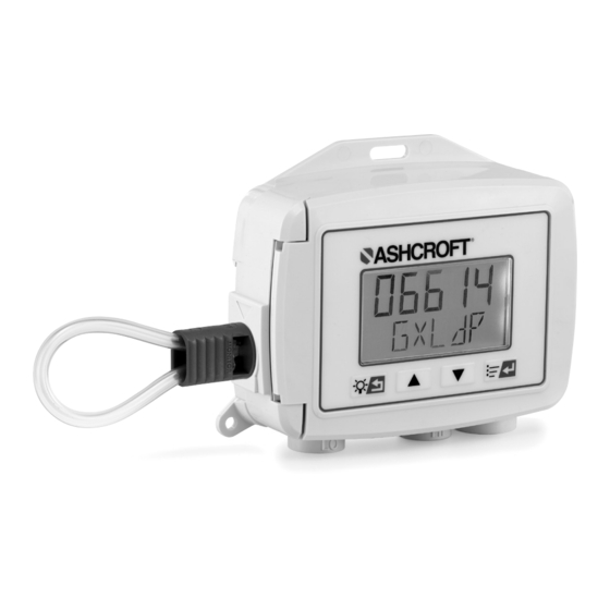
Installation and Operating
Instructions for GXLdp
Differential Indicating
Pressure Transmitter
Ashcroft Inc. 250 East Main Street, Stratford, CT 06614 USA
Tel: 203-378-8281, Fax: 203-385-0402 www.ashcroft.com
All sales subject to standard terms and conditions of sale.
© 2021 Ashcroft Inc. I&M011-10287_RevA_01-24-21
1
Advertisement
Table of Contents

Related Manuals for Ashcroft GXLdp


Summary of Contents for Ashcroft GXLdp
- Page 1 Installation and Operating Instructions for GXLdp Differential Indicating Pressure Transmitter Ashcroft Inc. 250 East Main Street, Stratford, CT 06614 USA Tel: 203-378-8281, Fax: 203-385-0402 www.ashcroft.com All sales subject to standard terms and conditions of sale. © 2021 Ashcroft Inc. I&M011-10287_RevA_01-24-21...
-
Page 3: Table Of Contents
TABLE OF CONTENTS Warnings/ General Information..............4 Keypad Functions & LCD Display..............5 Menu Functions/Programming..............6-14 Error Messages....................15 Display Resolution Table................16 Wiring Diagrams..................17-18 Specifications....................19 General Dimensions..................20 Panel Mount....................21... -
Page 4: Warnings/ General Information
INSTALLATION AND WIRING INSTRUCTIONS DESCRIPTION: Mounting: The Ashcroft Model GXLdp Differential In- The GXLdp transmitter can be mounted on dicating Pressure Transmitter is to be used a 35 mm DIN rail or with #8 or #10 screws with clean, dry, non-corrosive gases. The using the 3 mounting holes provided. -
Page 5: Keypad Functions & Lcd Display
ON or OFF displays depending on trip status of the switch. mA or Vdc will display depending on the selected Analog Output. 2W or 3W will display depending on if a 2-wire or 3-wire input power supply is connected to the GXLdp. -
Page 6: Menu Functions/Programming
The back button generally moves back the configuration/settings of the GXLdp: one screen in the menu. The back button also Units, Range, Output and Firmware version allows you to continue to move back until you... - Page 7 A OUT – Analog Output: Allows user to choose output signal. DAMP – Dampening: Allows user to vary the response time of the GXLdp output. The digital display and the analog output are both updated with the use of the DAMP function.
- Page 8 Menu/Enter . ‘SAVE’ will then be flashing. Press Menu/Enter The ‘RECAL’ function in the GXLdp menu pro- vides the user the ability to field calibrate the save this new selection and then you will return to the live display.
- Page 9 1. Press the Menu/Enter button scroll using the up or down arrow buttons display press the Menu/Enter button . This will return the GXLdp to the until ‘RECAL’ is flashing on the display. Press the Menu/Enter Button main menu and the NEW calibration will not be saved.
- Page 10 Menu/Enter SWITC: Switch function which will return you to the main menu. The GXLdp is available with an optional switch function. If ordered this feature will RESET: allow the user to choose between 1 or 2 PNP...
- Page 11 , this will cause SpoolCal actuator tool. In the CAL (Cali- the first digit to flash. brate) mode, the GXLdp is isolated from the 12. To change this digit press the up or process and allows externally generated test down arrow buttons pressure input for calibration.
- Page 12 GXLdp SPOOL CAL OPERATION ™ From the ‘OFF’ position, the SpoolCal™ actuator tool can be inserted and removed. Rotate the actuator tool 90° clockwise for Calibration mode (CAL) or 90° counter clockwise for Monitor mode (MONITOR) ROTATE KEY 90° CLOCKWISE TO...
- Page 13 11. Using the external pressure source, 5. This will restore the most recent factory increase the pressure to the full-scale value calibration. of the GXLdp. Then scroll using the up or down arrow buttons until the display reads the same as the pressure reference.
- Page 14 CANCL. With ‘CANCL’ flashing on the A 90-degree counterclockwise rotation tee’s display press the Menu/Enter button the process to both the GXLdp unit and out .This will return the GXLdp to the through the SpoolCal™ actuator tool, and main menu and the unit will maintain its provides external measurement capability most recent calibration.
-
Page 15: Error Messages
GXLdp Error Messages Note: Multiple Errors may be displayed. Configuration Error. Mismatch between sensor serial number Err02 on the sensor board and the sensor serial number recorded on the display board. FATAL ERROR. Calibration Error. Device has not been factory calibrated or the Err03 factory calibration data is corrupt. -
Page 16: Display Resolution Table
GXLdp Display Resolution Table in. H O Unidirectional in. H O Bidirectional 0.10 in. H 0.0000 0.1000 (±) 0.05 in. H -0.0500 0.0500 0.20 in. H 0.0000 0.2000 (±) 0.10 in. H -0.1000 0.1000 0.25 in. H 0.0000 0.2500 (±) 0.25 in. H -0.2500... -
Page 17: Wiring Diagrams
2 Wire 4-20mA GXLdp Wiring Diagrams 2 Wire 4-20mA Output Vout Power Optional Low-Side current − 3 Wire 4-20mA without switch sense shown in dashed lines 3 Wire 4-20mA Output Vout Power − 3 Wire 4-20mA Output w/PNP Switches Vout... - Page 18 3 Wire Voltage Output GXLdp Wiring Diagrams 3 Wire Voltage Output V− Vout Power − − Vdc/Vac 3 Wire Voltage Output With NPN Switches V− Vout 3 Wire Voltage Output With NPN Switches 30Vdc/50mA Max 30Vdc/50mA Max Power NPN Load NPN Load −...
-
Page 19: Specifications
UL 94-V0 Flame-retardant ABS, IP67/Nema 4 Burst Pressure: 25 psid Process Media: Zero Adjustment: The GXLdp is designed to measure clean, dry ±5% of span (accessible through menu) non-corrosive gases. Not for use with liquids. Span Adjustment: Weight: 0.8 lbs ±5% of full scale value (accessible through... -
Page 20: General Dimensions
GXLdp GENERAL DIMENSIONS R.10 2.70 4.09 1.45 5.14 1.86 2.68 2X Ø .20 1.34 TYP. 1.95 1.59. 5.49. R5.24 150° 1.67 ROTATE KEY ROTATE KEY 1.40 COUNTER-CLOCKWISE CLOCKWISE 5.93 'MONITOR' 'OFF' SPOOL-CAL POSITION SPOOL-CAL POSITION HIGH SIDE 1.00 [25.5] 1.71 [43.3]... -
Page 21: Panel Mount
GXLdp PANEL MOUNTING INSTRUCTIONS & DIMENSIONS To install the unit to the panel mounting: 1. Make a cutout 7˝ minimum vertical x 5.9˝ minimum horizontal in your panel or mounting location. 2. Provide (4) 6-32 threaded holes as shown in the drawings below. - Page 24 Ashcroft Inc. 250 East Main Street, Stratford, CT 06614 USA Tel: 203-378-8281, Fax: 203-385-0402, www.ashcroft.com All sales subject to standard terms and conditions of sale. © 2021 Ashcroft Inc. I&M011-10287_RevA_01-24-21...
Need help?
Do you have a question about the GXLdp and is the answer not in the manual?
Questions and answers