Table of Contents
Advertisement
Operator's Manual
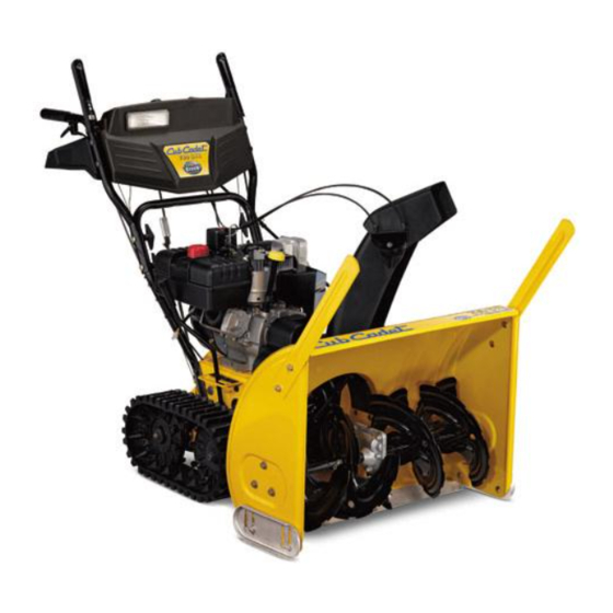
SNOW THROWER
MODEL 730 STE
IMPORTANT: READ SAFETY RULES AND INSTRUCTIONS CAREFULLY
WARNING:
This unit is equipped with an internal combustion engine and should not be used on or near any unimproved forest-
covered, brush-covered or grass-covered land unless the engine's exhaust system is equipped with a spark arrester meeting applicable local
or state laws (if any). If a spark arrester is used, it should be maintained in effective working order by the operator. In the State of California the
above is required by law (Section 4442 of the California Public Resources Code). Other states may have similar laws. Federal laws apply on
federal lands. A spark arrester for the muffler is available through your nearest engine authorized service dealer or contact the service
department, P.O. Box 361131 Cleveland, Ohio 44136-0019.
CUB CADET LLC, P.O. BOX 361131 CLEVELAND, OHIO 44136-0019
. 769-01887.fm
FORM NO
PRINTED IN U.S.A.
(5/2005)
Advertisement
Table of Contents

Related Manuals for Cub Cadet 730 STE


Summary of Contents for Cub Cadet 730 STE
-
Page 1: Snow Thrower
A spark arrester for the muffler is available through your nearest engine authorized service dealer or contact the service department, P.O. Box 361131 Cleveland, Ohio 44136-0019. CUB CADET LLC, P.O. BOX 361131 CLEVELAND, OHIO 44136-0019 . 769-01887.fm FORM NO PRINTED IN U.S.A. -
Page 2: Table Of Contents
You can locate the model plate by standing at the operating position and looking down at the rear of the snow thrower. This information will be necessary to use the manufacturer’s web site and/or obtain assistance from an authorized Cub Cadet dealer. CUB CADET LLC P. -
Page 3: Section 1: Important Safe Operation Practices
SECTION 1: IMPORTANT SAFE OPERATION PRACTICES WARNING: This symbol points out important safety instructions which, if not followed, could endanger the personal safety and/or property of yourself and others. Read and follow all instructions in this manual before attempting to operate this machine. Failure to comply with these instructions may result in personal injury. -
Page 4: Your Responsibility
20. If situations occur which are not covered in this manual, use care and good judgment. Contact the dealer you purchased the unit from or call 1-877-282-8684 for the name of your nearest Cub Cadet service dealer. Maintenance & Storage Never tamper with safety devices. Check their proper operation regularly. -
Page 5: Loose Parts
SECTION 1: ASSEMBLING YOUR SNOW THROWER Unpacking • Remove screws from the top sides and ends of the shipping crate. • Set panel aside to avoid tire punctures or personal injury. • Remove and discard plastic bag that covers unit. •... -
Page 6: Section 2: Know Your Snow Thrower
Cable Discharge Chute Figure 3 • If not already attached, unwrap the headlight wire which is attached to the headlight, beneath the handle panel. Wind the headlight wire around the lower right handle until excess slack is removed. See Figure 4. SECTION 2: KNOW YOUR SNOW THROWER Drive Control / Auger Control Lock... -
Page 7: Skid Shoe
The drive control also locks the auger control so you turn chute directional interrupting the snow throwing process. If the auger control is engaged along with the drive control, the operator can release the auger control (on the left handle) and the augers will remain engaged. Release both controls to stop the augers and track drive. -
Page 8: Before Starting
Track Lock Lever The track lock lever is located on the right side of the snow thrower and is used to select the position of the auger housing and the method of track operation. Move the lever to the right, then forward or backward to one of the three positions. -
Page 9: To Stop Engine
• Rotate choke knob to FULL choke position (cold engine start). If engine is warm, place choke in OFF position instead of FULL. • Push primer button two or three times for cold engine start, making sure to cover vent hole in primer button when pushing. -
Page 10: Operating Tips
If the auger shows ANY signs of rotating, IMPORTANT: immediately return to the operator’s position and shut off the engine. Wait for ALL moving parts to stop before re-adjusting the auger control. • To readjust the control cable, loosen the hex jam nut on the auger control cable “Z”... -
Page 11: Chute Assembly
SECTION 4: MAKING ADJUSTMENTS WARNING: NEVER attempt to make any adjustments while the engine is running, except where specified in the operator’s manual. Chute Assembly The distance snow is thrown can be adjusted by changing the angle of the upper chute. Move the chute tilt control forward to decrease the distance, toward the rear to increase. -
Page 12: Shift Rod Adjustment
Shift Rod Adjustment To adjust the shift rod, proceed as follows: • Remove the hairpin clip and slide the shift rod connector up, to separate the upper shift rod from the lower shift rod. See Figure 11. • Place the shift lever into the sixth (6) position. •... - Page 13 WARNING: If any adjustments need to be made to the engine while the engine is running (e.g. carburetor), keep clear of all moving parts. Be careful of muffler, engine and other surrounding heated surfaces. Drive / Auger Control Lock The cams on the ends of the control rods which interlock the drive and auger controls must be lubricated at least once a season or every 25 hours of operation.
-
Page 14: Belt Removal And Replacement
SECTION 6: SERVICING YOUR SNOW THROWER WARNING: Before servicing, repairing, or inspecting, disengage all controls and stop engine. Wait until all moving parts have come to a complete stop. Disconnect spark plug wire and ground it against the engine to prevent unintended starting. -
Page 15: Replacing Friction Wheel Rubber
• Tip the snow thrower up and forward so that it rests on its auger housing. Refer to Figure 9. • Remove the six self-tapping screws from the frame cover underneath the snow thrower. • Roll the front and rear auger belts off the engine pulley. -
Page 16: Off-Season Storage
• Using a 7/8" wrench to hold the shaft, loosen, but do not completely remove, the hex bolt and bell washer on the left end of gear shaft. See Figure 20. Hex Bolt & Bell Washer Track Figure 20 • Lightly tap the hex nut to dislodge the ball bearing from the right side of frame before removing the hex nut and bell washer from left end of shaft. -
Page 17: Section 7: Troubleshooting
Stop the engine immediately and disconnect the spark plug wire. Tighten all bolts and nuts. If vibration continues, have the unit serviced by an authorized Cub Cadet service dealer. Adjust drive control cable. Refer to Making Adjustment Section. Replace drive belt. Refer to the Service Section. -
Page 18: Section 8: Parts List For Model 730 Ste
SECTION 8: PARTS LIST FOR MODEL 730 STE Part of handle panel for reference only... - Page 19 Model 730 STE Part No. Part Description 684-0008A Shift Arm Assembly 705-5204A Chute Directional Control 710-0449 Carriage Screw 5/16-18 x 2.25 710-0458 Carriage Bolt 5/16-18 x 1.75 710-0643 Hex Bolt 5/16-18 x 1.0 710-0788 TT Screw 1/4-20 x 1.0 710-1880 Hex Bolt 5/16-18 x 0.75...
- Page 20 Model 730 STE...
- Page 21 Model 730 STE Ref. Part No. Part Description 714-04040 Cotter Pin 756-0178 Flat Idler 784-5632B Auger Idler Arm 710-0347 Hex Cap Screw 3/8-16 x 1.75 738-0281 Shoulder Screw 736-0174 Wave Washer 732-0611 Extension Spring 712-3068 Hex Nut 5/16-18 710-0642 Self Tapping Screw, 1/4-20 x.75 711-04282 Auger Axle, 30”...
- Page 22 Model 730 STE 32 32 30 31...
- Page 23 Model 730 STE Ref. Part No. Part Description 784-5648 Frame Cover 710-1652 AB Screw 1/4-20 x.625 748-0190 Spacer 732-0264 Extension Spring 712-0711 Jam Nut 3/8-24 736-0105 Bell Washer 684-0021 Friction Whl Support Bracket Ass’y 746-0898B Drive Cable 656-0012A Friction Disc...
- Page 24 Model 730 STE...
- Page 25 Model 730 STE Ref. Part No. Part Description 720-0223 Grip 710-0604A Tap Screw, 5/16-18 x.625 784-5642 Track Lockout Plate 710-0157 Hex Cap Screw, 5/16-24 x.75 736-0242 Bell Washer 684-0038 Track Lock Handle Assembly 710-0459A Hex Cap Screw, 3/8-24 x 1.5...
- Page 26 Model 730 STE IMPORTANT: For a proper working machine, use Factory Approved Parts. V-BELTS are specially designed to engage and disengage safely. A substitute (non OEM) V-Belt can be dangerous by not disengaging completely Ref. Part No. 710-1652 Hex Washer Screw 1/4-20 x.625...
-
Page 27: Commercial Warranty
Log splitter pumps, valves, and cylinders have a separate one- year warranty. Cub Cadet LLC, P.O. BOX 361131 CLEVELAND, OHIO 44136-0019; Phone: 1-866-840-6483, 1-330-558-7220 MTD Canada Limited - KITCHENER, ON N2G 4J1; Phone 1-800-668-1238 FOR: Routine maintenance items such as lubricants, filters,... -
Page 28: Residential Warranty
MANUFACTURER’S LIMITED WARRANTY FOR: The limited warranty set forth below is given by Cub Cadet LLC with respect to new merchandise purchased and used in the United States, its possessions and territories, and by MTD Products Limited with respect to new merchandise purchased and used in Canada and/or its territories and possessions.
Need help?
Do you have a question about the 730 STE and is the answer not in the manual?
Questions and answers