Table of Contents
Advertisement
Quick Links
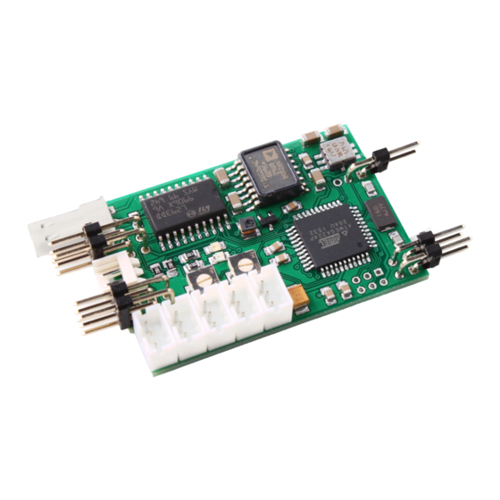
TVC-GSU-11
TVC-GSU-11
gun stabilizer module for models with Tamiya DMD T-07
The module has been specifically designed to incooperate the Tamiya DMD
T-07's for Leopard 2A6 model. The module stabilizes the horizontal and
the vertical movement of the gun. This is acccomplish by using modern
gyro- and inertialsensor technology.
The module can be operated so that there is no further RC channel needed.
This allows 4 channel transmitters to (with the necessary for the DMD
mechanical trimmers) can be used are used. Alternatively, one chanel can
be used to activate the stabilization, the horizontal and vertical sensitivity
via transmitter. Then up to three additional channels are needed.
1
© SGS electronic 2006-2024
Advertisement
Table of Contents

Related Manuals for SGS electronic TVC-GSU-11


Summary of Contents for SGS electronic TVC-GSU-11
- Page 1 This allows 4 channel transmitters to (with the necessary for the DMD mechanical trimmers) can be used are used. Alternatively, one chanel can be used to activate the stabilization, the horizontal and vertical sensitivity via transmitter. Then up to three additional channels are needed. © SGS electronic 2006-2024...
- Page 2 Always switch off power when working on the wiring. Especial take care when connecting more than one receiver energy source. Prevent the device from getting wet. Check loads before connecting them to the modul at a current limited, or fuse protected source. © SGS electronic 2006-2024...
-
Page 3: Table Of Contents
10.1 Warning ........25 © SGS electronic 2006-2024... - Page 4 ......20 Abbrevation for the manipulators in the transmitter housing 23 © SGS electronic 2006-2024...
-
Page 5: Overview
• y-style power supply adapter with Tamiya battery connectors . The adapter can be used with a seperate battery or can be plugged be- tween main battery and DMD unit. • 2,54mm jumper for programming • 2,54mm jumper for orientation selection © SGS electronic 2006-2024... - Page 6 TVC-GSU-11 • 2mm jumper for shortening the rear deflector switch within the DMD © SGS electronic 2006-2024...
-
Page 7: Functional Description
3.3 Automatic Stabilization of the Gun Elevation If the stabilization is active, the vertical orientation of the tower will be automatic maintained by the module. © SGS electronic 2006-2024... - Page 8 The sensitivity of the control can be adapted to the model. This can either be done remote using a proportional channel on the radio, or through a trimmer on the module. © SGS electronic 2006-2024...
-
Page 9: Installation
Figure 1: From our point of view the best position to mount the module in a Leopard 2A6. A ABS base plate has been glued onto the housing of the turret turn motor.Then the module is attached with double-sided adhesive tape. © SGS electronic 2006-2024... -
Page 10: Location Of The Module In The Tower Of The Leopard 2A6
• Leopard 2A6: The green jumpers must be in the direction of the main gun. X12 remains open. • Leopard 2A5: The green jumpers must be aligned to the right (from the main weapon’s point of view). X12 is plugged © SGS electronic 2006-2024... -
Page 11: Connections
J5 of the DMD stabilization on / receiver channel switching the control sensitivity gun receiver channel sensitivity gun elevation elevation sensitivity turret receiver channel sensitivity tur- rotation ret rotation © SGS electronic 2006-2024... -
Page 12: Stabilization On / Off
/ slider. If no receiver signal is detected there (and only then), the input X14 will be evaluated. Are the contacts connected by X14 is the stabilization active. If the contacts © SGS electronic 2006-2024... -
Page 13: Tower Rotation
X5. The inertia of the gun elevation (X10) can be set via a proportional channel. After switching on the inertia is 50% of the maximum value. If X10 is © SGS electronic 2006-2024... -
Page 14: Power Supply Of The Module
Vertical axis. Therefore, the weapon stabilization can not keep track when driving fast. The drive motor for the tower rotation is too slow. To achieve higher dynamics in the tower rotation, the tower rotary motor © SGS electronic 2006-2024... - Page 15 TVC-GSU-11 can be operated with a higher voltage. In this case, an additional Battery with higher voltage is connected to the weapon stabilizer. Alternatively, a motor with higher power can be installed. © SGS electronic 2006-2024...
-
Page 16: Example Radio Assignment
DMD J2 Throttle gun up / down DMD J3 GUN turret left / right GSU11 X7 stabilization on / off GSU11 X9 sensitivity gun elevation GSU11 X10 sensitivity tower rotation GSU11 X11 Table 4: Assignment of the recipient © SGS electronic 2006-2024... -
Page 17: Channel Assignment In The Transmitter
/ right drive forward / backwards cannon up / down P4+S7+8 tower left / right P3+S5+6 control on / off S1+2 sensitivity gun elevation sensitivity turret Table 5: Channel assignment in the transmitter © SGS electronic 2006-2024... -
Page 18: Commissioning
5. the LED1 (red) lights up 6. The LED2 (green) flashes until the controller detects the center posi- tion of the channels. If the zero point detection is not possible, the LED does not light up. © SGS electronic 2006-2024... -
Page 19: Operation
The calibration process takes about five seconds. 6.2.2 Operation The switch-on process is the same as for the calibration. Only is the jumper not plugged. Check if you can turn stabilization on and off. The LED2 (green) indicates this. © SGS electronic 2006-2024... -
Page 20: Problems And Causes
J19 of the DMD position The cradle moves during stabiliza- Check the seat of the rear deflector tion and manual control not below contact at X4 the 0 degree position Table 6: problems and causes © SGS electronic 2006-2024... -
Page 21: Options
In addition, the TVC-GSU11 has to consider some DMD T-07 special features (regarding the kind of using the trimmers), which are not needed in models without DMD. © SGS electronic 2006-2024... -
Page 22: Glossary Of Terms
Scalebus The Scalebus is a development of SGS electronic to connect con- trollers and modules to compose solutions for complex RC models. -
Page 23: Abbrevation For The Manipulators In The Transmitter Housing
Switch Three Stage switch with three stages Switch Potentiometer linear- or rotary knob PotC Potentiometer linear- or rotary knob with a center key with Center key Table 7: Abbrevation for the manipulators in the transmitter housing © SGS electronic 2006-2024... -
Page 24: Technical Data
TVC-GSU-11 9 Technical Data Nennspannung 6-24V Nenn-Motorstrom 5 Ampere PWM Frequenz 2kHz Abmessungen 40x70x10mm Softwareversion V0.8.2 © SGS electronic 2006-2024... -
Page 25: Important
Electronic devices do not belong in household waste. © SGS electronic 2006-2024... -
Page 26: Address
We reserve the right to make updates, changes or additions to the infor- mation and data provided. The documentation that accompanies your product applies. Please note that documents obtained later via download may not corre- spond to the status of your module. © SGS electronic 2006-2024... - Page 27 TVC-GSU-11 © SGS electronic 2006-2024...
- Page 28 TVC-GSU-11 © SGS electronic 2006-2024...
Need help?
Do you have a question about the TVC-GSU-11 and is the answer not in the manual?
Questions and answers