Table of Contents
Advertisement
Quick Links
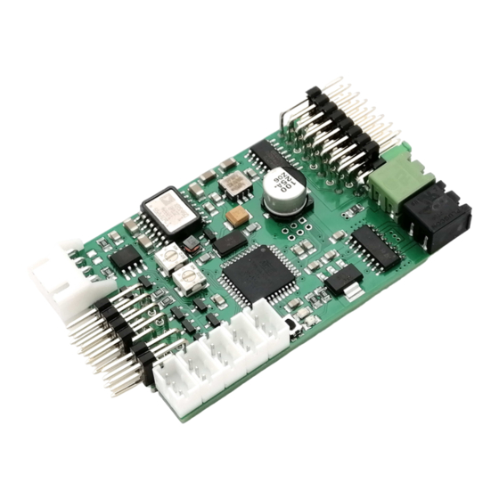
TVC-GSU-12
TVC-GSU-12
gun stabilizer module for rc main battle tanks
The module stabilizes the horizontal and the vertical movement of the
gun in a radio controlled main battle tank model. This is acccomplish by
using modern gyro- and inertialsensor technology. As soon as this sticks
are released to return to neutral, this is stored as the new position to be
stabilized.
The gun elevation is controlled by a servo, the tower rotation by a geared
motor placed in the turret. A speed controller with 5A continuous load is
already integrated to control the tower rotation motor.
The modul simulates the barrel retraction, too. A servo or a motor driven
unit can be used to realize this.
The device can simulate the autoloader automatic move to the loading
position and return to the initial position.
A back rear collision avoidance input lifts the barrel automatic to a settable
hight, to avoid collision of the barrel with the hull.
The modul can be operated with a rc receiver or using the SGS Scalebus
connection. Scalebus Operation additionally controls the periscope and a
machine gun turret (urban fighting PSO variant).
1
© SGS electronic 2006-2024
Advertisement
Table of Contents

Related Manuals for SGS electronic TVC-GSU-12


Summary of Contents for SGS electronic TVC-GSU-12
- Page 1 The modul can be operated with a rc receiver or using the SGS Scalebus connection. Scalebus Operation additionally controls the periscope and a machine gun turret (urban fighting PSO variant). © SGS electronic 2006-2024...
- Page 2 Always switch off power when working on the wiring. Especial take care when connecting more than one receiver energy source. Prevent the device from getting wet. Check loads before connecting them to the modul at a current limited, or fuse protected source. © SGS electronic 2006-2024...
-
Page 3: Table Of Contents
4.8 autoloader simulation ......23 5 Commissioning 5.1 Important notes ......24 © SGS electronic 2006-2024... - Page 4 Assignment of the Heng Long flash unit ....21 Connecting the HL and Tamiya flash unit to the module ..21 Connection for flash units with negative trigger pulse ..21 © SGS electronic 2006-2024...
- Page 5 Belegung Motor, Servo, Akkuverbinder ....19 LED Flash codes when setting the barrel positions ..27 Abbrevation for the manipulators in the transmitter housing 32 © SGS electronic 2006-2024...
-
Page 6: Functional Description
The sensitivity of the control can be adapted to the model. This can either be done remote using a proportional channel on the radio, or through a trimmer on the module. © SGS electronic 2006-2024... -
Page 7: Firing The Main Weapon
Electro Mechanical Systems), i. the micro mechanical gyro / inertia system is completely in implemented a semiconductor. A gyroscope is used as the sensor for the rotation axis stabilization. The maximum detectable angular velocity is 300 . The sensor gives signal © SGS electronic 2006-2024... -
Page 8: Scope Of Delivery
2.7 Scope of Delivery • the module • black and green connector fro power supply and turret rotation motor • jumper for autoloader on/off • five plugable servo leads © SGS electronic 2006-2024... -
Page 9: Installation
The end positions of the levelling effect, the position of the autoloader and the position when lifting in the collision avoidance mode can be set electronically. (See commissioning) © SGS electronic 2006-2024... -
Page 10: Preconditions Servo Gun Recoil
The rest position and the position at maximum retraction can be set elec- tronically. (See commissioning) 3.4 Preconditions turret turn motor The tower rotation motor should be mounted in the turret, because the stabilisation module must be mounted in the turret. The turret rotation © SGS electronic 2006-2024... - Page 11 The gear ratio should be selected to match the originals speed when supplied with the battery voltage. In modern MBTs this typically 4 rpm equals approx. 15 seconds per revolution. © SGS electronic 2006-2024...
-
Page 12: Anschluss
As the module has its own BEC controller, it then supplies itself and the scale bus repeater from the battery for the turret. The servo cables can be disconnected during scale bus operation. © SGS electronic 2006-2024... -
Page 13: Receiver Connection
If channels X8 and X9 (and X10) are not connected to the receiver, the corresponding control information is expected from an FO module via the Scalebus. It is then not necessary to connect all five servo cables to the receiver. © SGS electronic 2006-2024... -
Page 14: Servo Cable Assignment
General note The receiver also acts as a power busbar via which all connected loads are connected. If there is now a second ESC with BEC in the model, two sources supply the receiver and all consumers connected © SGS electronic 2006-2024... -
Page 15: Connection Of The Tower Motor, Battery And Servos
Figure 5: Assignment of the plug connectors for servo outputs, battery connec- tion and tower motor 4.3.1 Connection of the tower motor A plug-in, black screw terminal (X13) is provided for the tower motor. To- gether with the gyro sensor, the tower motor forms a feedback control © SGS electronic 2006-2024... -
Page 16: Connecting The Battery
Note The motor must be interference-suppressed, as is usual in rc mod- elling. 4.3.2 Connecting the battery Fahrakku plus (+) Fahrakku minus (-) Figure 6: Assignment of the plug for the power supply © SGS electronic 2006-2024... -
Page 17: Jumper Servo Power Supply
The servo for the gun elevation is connected to X20, the servo for the barrel recoil to X19. In Scalebus mode, a servo for controlling the commander periscope can be connected to X18. It precedes the turret rotation OR the drive rotation. © SGS electronic 2006-2024... -
Page 18: Example Of A Gun Level And Retraction Unit With Servos
(e.g. by a stop on the linkage levers), high currents usually flow, which drive the BEC into the current limit and lead to a reset of the module. Figure 7: Example of a gun level and retraction unit with servos © SGS electronic 2006-2024... -
Page 19: Assignment Of The Plug Connectors For Inputs And Switching Outputs
X2 (e.g. for Heng Long high-voltage flash) and negatively switched on X3 (e.g. for Tamiya high-voltage flash). An electric motorised gun retraction can be connected to the RRZ output. This output is also available with positive and negative outputs. © SGS electronic 2006-2024... -
Page 20: Rkl, Mg, 20Mm Gun And Laser
When the shot is triggered, the LED is switched on for approx. 300ms. The output switches max. 500mA against battery plus. High-current (HiFlux) LEDs can also be connected. When using an LED it is essential to connect a resistor to limit the current. © SGS electronic 2006-2024... -
Page 21: High Tension Flasher
Figure 9: Assignment of the Tamiya Figure 10: Assignment of the Heng flash unit Long flash unit Figure 11: Connecting the HL and Figure 12: Connection for flash units Tamiya flash unit to the module with negative trigger pulse © SGS electronic 2006-2024... -
Page 22: Connection Of A Motorised Gun Recoil Unit
2nd motor connection via a switch to the continuous - (battery-). This switch ensures that the motor continues to run to the end position after receiving the start pulse. The output for the start impulse can be loaded with max. 500mA. © SGS electronic 2006-2024... -
Page 23: Installation Collision Avoidance Switch
After firing and recoil the gun, the module moves the gun to the loading position for approx. 1 second to simulate the loading process. If this function is not required, the jumper can be plugged into the position shown in figure 14. © SGS electronic 2006-2024... -
Page 24: Commissioning
Parametrisation is optional. Parametrisation is divided into two groups: 1. parametrisation mode for the tube positions for stops, loading and rear deflector position 2. parametrisation mode for the installation position and weapon re- lease The module operates with the following factory default settings: © SGS electronic 2006-2024... -
Page 25: Calibration
If zero point detection is not possible, LED1 does not light up. 7. The module now waits approx. 10 seconds for the button to be pressed. This is indicated by LED 1 and LED2 flashing alternately. © SGS electronic 2006-2024... -
Page 26: Settings
Otherwise the tube will not move after the end of settings mode. The double flashing can be recognised by the double flashing of LED2, after which LED1 lights up to indicate the start of a new cycle. © SGS electronic 2006-2024... -
Page 27: Led Flash Codes When Setting The Barrel Positions
8. the module moves the gun elevation to the last set position of the loading position and shows four flashes 9. Use the transmitter to move the height adjustment servo to the © SGS electronic 2006-2024... - Page 28 At the end of the barrel settings positions, you have the option of entering the settings mode for the installation position and gun triggering. At the end of the barrel settings positions, the module flashes alternately for approx. 10 seconds. During this time, you have the following options: © SGS electronic 2006-2024...
- Page 29 8. the module stops flashing and LED 1 lights up Settings aredone now and the module is ready for operation. The settings made are saved so that they are retained the next time the module is © SGS electronic 2006-2024...
-
Page 30: Turn On
1. When switching on, the module measures the zero point of the inertial sensors, so the model must be level when switching on. 2. The right-hand LED2 indicates whether stabilisation is active. 6 Optionen For Tamyia models with DMD-T07 we recommend the TVC-GSU-11. © SGS electronic 2006-2024... -
Page 31: Glossary Of Terms
Scalebus The Scalebus is a development of SGS electronic to connect con- trollers and modules to compose solutions for complex RC models. -
Page 32: Abbrevation For The Manipulators In The Transmitter Housing
Switch Three Stage switch with three stages Switch Potentiometer linear- or rotary knob PotC Potentiometer linear- or rotary knob with a center key with Center key Table 5: Abbrevation for the manipulators in the transmitter housing © SGS electronic 2006-2024... -
Page 33: Technische Daten
Versorgungsspannung (ohne BEC) 5 bis 24 V Versorgungsspannung (mit BEC) 6,5 bis 24 V Zulässiger BEC Strom 800mA PWM Frequenz 8kHz Typische maximale Verlustleistung 25 Watt Typischer Spannungsabfall in der Endstufe 1.5 Volt Abmessungen 62x41x18mm Softwareversion 28.0e.78 © SGS electronic 2006-2024... -
Page 34: Important
Electronic devices do not belong in household waste. © SGS electronic 2006-2024... -
Page 35: Address
We reserve the right to make updates, changes or additions to the infor- mation and data provided. The documentation that accompanies your product applies. Please note that documents obtained later via download may not corre- spond to the status of your module. © SGS electronic 2006-2024... - Page 36 TVC-GSU-12 © SGS electronic 2006-2024...
Need help?
Do you have a question about the TVC-GSU-12 and is the answer not in the manual?
Questions and answers