
Related Manuals for SGS electronic TVC-TRF-10-MBT


Summary of Contents for SGS electronic TVC-TRF-10-MBT
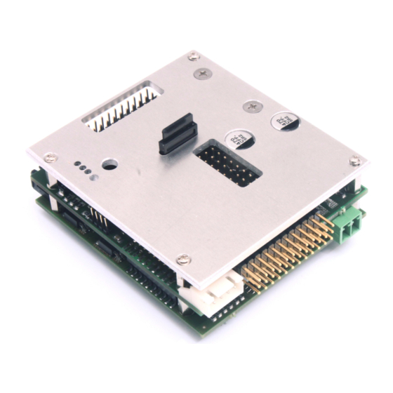
- Page 1 TVC-TRF-10-MBT TVC-TRF-10-MBT Full option module with sound for RC-battle tanks in 1/16th to1/25th scale This module was developed to enable complete control of battle tanks. © SGS electronic 2006-2021...
- Page 2 Always switch off power when working on the wiring. Especial take care when connecting more than one receiver energy source. Prevent the device from getting wet. Check loads before connecting them to the modul at a current limited, or fuse protected source. © SGS electronic 2006-2021...
-
Page 3: Table Of Contents
Rotating flasher light ..... . 3.4.4 Turn signals ......© SGS electronic 2006-2021... - Page 4 7.6 Connecting LED ......8 Glossary of terms 9 Technical data 10 Important © SGS electronic 2006-2021...
- Page 5 ..... . Abbrevation for the manipulators in the transmitter housing . . © SGS electronic 2006-2021...
-
Page 6: Introducing
• 4 inputs for sensors (e.g. gepard radar parking pos sensor) • maximum control chanel count is 16; PPM, S-Bus, I-Bus are supported • sounds and firmware can be loaded using a uSD card to change the © SGS electronic 2006-2021... -
Page 7: Technology
LED • FO-AD13 universal adapter with contact spring force clamps • TVC-TRF-AD4 Adapter for connectors of the electrical system in Tamiya truck models 2.5 Overview 2.5.1 build in functions This module will provide the following functions: © SGS electronic 2006-2021... -
Page 8: Additional Options
For endless turret rotation, wiring can be eliminated by using GFMC-SBR10 scalebus repeater. In this case the turret drives and lights are connected to TVC- GSU-12 (with stabilization) or turret control TVC-TC12 (without stabilization). © SGS electronic 2006-2021... -
Page 9: Radio Requirements
(all) intended to directly output their switching state. Their primary task in flight radios is to manipulate the function / parameters of the mixers built into the transmitter. The failsafe function (if available) should be set to output the mid position of all chanels. © SGS electronic 2006-2021... - Page 10 As the switch don’t move if you let him go, the servo will not move also. 4. using a three stage momentary switch a servo can also the moved to three positions, mut it returns to mid after releasing the switch. © SGS electronic 2006-2021...
-
Page 11: Functions
Combied elevation/gun trigger on channel 3 is inactive, if the dedicated trigger channel 8 is used. In this case channel 3 only moves the gun vertically. 3.1.4 Channel 4 Proportional turret rotation © SGS electronic 2006-2021... -
Page 12: Channel 5 Controlling The Light Mode
To limit the channels need, firing and gun elevation is combinded on chanel 3. If your radio has enough channels, you can trigger the gun with this dedicated channel. In this case the double function of chanel 3 is deactivated and it is only used for elevation control. © SGS electronic 2006-2021... -
Page 13: Function Of The Light Mode Control
The mode is count up , (1 1 and so on). When keeping the stick for about 2 seconds, the lightmode is reset to 1(all off). Zustand auxlight 1 auxlight 2 Table 2: Lightmode 1 © SGS electronic 2006-2021... -
Page 14: Lightmode 2
When the model is parked by turning of the transmitter, all light are turned off. When using the battle-system, the four rotating lights are also activated in a random way for about three seconds when the tank is hit by the battlesystem. © SGS electronic 2006-2021... -
Page 15: Tip 2
When the module is parking mode, random sounds are played. E.g. this can be sound from construction machines, music or walkie talky noise. These sounds, like all others on the module, can be changed. © SGS electronic 2006-2021... -
Page 16: Drive-Dynamic Functions
3.4.4 Turn signals Starting from a minimum of 10% throttle the signal lights will flash left or right as required. Das Warnblinklicht kann durch den Lichtmodus 2 ein- oder ausgeschaltet werden. © SGS electronic 2006-2021... -
Page 17: Brake Light
TVC-TRF-10-MBT 3.4.5 Brake light The brake light is automatic. Lights go out automatically with resumed throttle. © SGS electronic 2006-2021... -
Page 18: Connector Overview
Figure 1: connector overview 4.1 Connection of batteries cable (X60) The connection is made with the green contact block. The connector is (X60). It is a good practice to install a switch between battery and the power connector. © SGS electronic 2006-2021... -
Page 19: Connection To The Receiver (X50 To X511)
BEC unit. This may lead into damage if one of the BEC units is a switching voltage regulator (SBEC). In this case pull the +5V (red( cable from all servo cables and isolate them with a tape or shrink wrap. © SGS electronic 2006-2021... -
Page 20: Connection Of The Servo Outputs (X40 To X47)
Parallel to the esc output for turret rotation a servo output (X42) is controlled. This simplifies control for models with small deflection like ”Jagdpanzer” or Howitzer tanks. The servo functions are damped to provide realistic movements. The speed and direction are proportional to stick deflection. © SGS electronic 2006-2021... -
Page 21: Connect The Cannon Elevation Servo
The servo for the recoil is connected to X40. Figure 7: example mechanic tor recoil and elevation 4.4 connection of the motors (X01 - X04 & X20 - X21) motors are connected with blach, plugabble connectors. © SGS electronic 2006-2021... -
Page 22: Connection Of Drive Motors
X21. 4.6 connection of the switch outputs (X08 to X17) The switch outputs are used for light- and simple motor functions. Each con- nector has two outputs (blue and grey) and one common connection (red). © SGS electronic 2006-2021... -
Page 23: Connection Of Lighting And Exhaust Systems
Example: If the model is operated with a 12V battery, the connected load should be rated for 12Volt. LEDs must be equipped with suitable resistors. The heater from the exhaust system can be connected to X04,too. This output is able to drive up to 5A. © SGS electronic 2006-2021... -
Page 24: Connecting The Speaker (X70)
The volume may be adjusted by a RC channel or the potentiometer (V1). Use a 2mm screw driver to operate the volume control. When the volume is controlled by a rc channel, the potentiometer (V1) has no function. Figure 10: speaker connector © SGS electronic 2006-2021... -
Page 25: Connecting The Battle Unit (X510 And X511)
(X511). Figure 11: TVC-BU12 Tip The TVC-HRF-AD3 adapter has been designed to match the Heng Long cabling. The HL connectors fit the headers on the board including the HL Battle System connectors. © SGS electronic 2006-2021... -
Page 26: Tvc-Hrf-Ad3 Heng Long Adapter Mounted On The Fo Module
TVC-TRF-10-MBT Figure 12: TVC-HRF-AD3 Heng Long adapter mounted on the FO module © SGS electronic 2006-2021... -
Page 27: Initialization
The green LED 3 on the module shows the active operation mode. The LED flashes like this. 1 flash normal drive mode 2 flashes parking mode 3 flashes model unselected (passive) 4 flashes destroyed (battle unit) 5 flashes damaged (battle unit) 6 flashes invulnerable (battle unit) © SGS electronic 2006-2021... -
Page 28: Changing Sound And Software
LED. This sequence takes roughly 30 to 60 seconds. After powering down the module, the µSD card can be removed. It is not needed for operation. Always power off the module before the µSD Card is removed . Figure 13: position and orientation of the µSD card slot © SGS electronic 2006-2021... -
Page 29: Changing The Software
6.3.1 Vulnerably Depending on the type of model, it reacts differently to the fire of other models. This is to simulate the different armor of various types of tanks. The more hits © SGS electronic 2006-2021... -
Page 30: Resetting The Damage Grade
As described above, the model ill get limited in its mobility by enemy fire. To do not influence the game, no limitations to the duration of the states are made. But case the game is stopped by your combat partner, the player’s own model remains back with limited mobility. © SGS electronic 2006-2021... -
Page 31: Delay Used By The Battle Unit
Turn the model off and on again Tip Please keep in mind that the first way can not work if you use failsafe receivers. © SGS electronic 2006-2021... -
Page 32: Practical Tips
Isolate open connections using shrink hose or tape. 7.4 Work on the wiring turn off your model completely when working at the wiring. Do not plug connectors while the model is powered. © SGS electronic 2006-2021... -
Page 33: Rotating Flasher
When connecting LED, please use suitable resistors. On page 34 correct way to calculate the resistor value is show. Common resistors are within the scope of delivery . Note Please never connect LED without resistor to the module. This will destroy the LED and/or the module. © SGS electronic 2006-2021... -
Page 34: Led Resistor
LEDs and 7,2V batterie: 7, 2V 1, 2V 0, 02A = 240Ω The Summe of the Forward voltages should be min. 2V under the battery voltage. If more LEDs are needed, just switch groups in parallel. © SGS electronic 2006-2021... -
Page 35: Glossary Of Terms
Scalebus The Scalebus is a development of SGS electronic to connect con- trollers and modules to compose solutions for complex RC models. -
Page 36: Technical Data
11 pb cells / max 12 NiCd/NiMh cells / max 4S Lipo) rated current BEC servo outputs 1000mA rated current BEC receiver output 800mA maximum power disapation 5 Watt maximum operation temperature 75°C diemnsions without connectors 65x75x34mm © SGS electronic 2006-2021... -
Page 37: Important
(causing a short circuit). 10.1 Address SGS electronic Zeppelinstraße 36 47638 Straelen Germany / Europe 10.2 Contact www.sgs-electronic.de Email info@sgs-electronic.de Ust-IdNr.: DE 249033623 WEEE-Reg.-Nr.: DE 90290947 10.3 Document date This document has been created on 25.01.2021, 12:35:31 MEZ . © SGS electronic 2006-2021... - Page 38 TVC-TRF-10-MBT © SGS electronic 2006-2021...
- Page 39 TVC-TRF-10-MBT © SGS electronic 2006-2021...
- Page 40 TVC-TRF-10-MBT © SGS electronic 2006-2021...
Need help?
Do you have a question about the TVC-TRF-10-MBT and is the answer not in the manual?
Questions and answers