Table of Contents
Advertisement
Quick Links
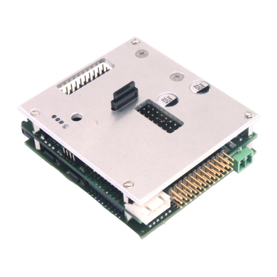
TVC-TRF-10-AAT
TVC-TRF-10-AAT
Full option module with sound for RC-battle tanks in
1/16th to1/25th scale
This module was developed to enable complete control of Gepard Flak-
panzer. It can also control other modern air defense tracked vehicles such as
Roland or the Tunguskta (USSR).
1
© SGS electronic 2006-2021
Advertisement
Table of Contents

Related Manuals for SGS electronic TVC-TRF-10-AAT


Summary of Contents for SGS electronic TVC-TRF-10-AAT
- Page 1 Full option module with sound for RC-battle tanks in 1/16th to1/25th scale This module was developed to enable complete control of Gepard Flak- panzer. It can also control other modern air defense tracked vehicles such as Roland or the Tunguskta (USSR). © SGS electronic 2006-2021...
-
Page 2: Note
Always switch off power when working on the wiring. Especial take care when connecting more than one receiver energy source. Prevent the device from getting wet. Check loads before connecting them to the modul at a current limited, or fuse protected source. © SGS electronic 2006-2021... -
Page 3: Table Of Contents
Turn signals ......3.4.5 Brake light ......© SGS electronic 2006-2021... - Page 4 10.2 Contact ........10.3 Document date ......© SGS electronic 2006-2021...
- Page 5 ......Abbrevation for the manipulators in the transmitter housing . . © SGS electronic 2006-2021...
-
Page 6: Introducing
• 4 inputs for sensors (e.g. gepard radar parking pos sensor) • maximum control chanel count is 16; PPM, S-Bus, I-Bus are supported • sounds and firmware can be loaded using a uSD card to change the © SGS electronic 2006-2021... -
Page 7: Technology
LED • FO-AD13 universal adapter with contact spring force clamps • TVC-TRF-AD4 Adapter for connectors of the electrical system in Tamiya truck models 2.5 Overview 2.5.1 build in functions This module will provide the following functions: © SGS electronic 2006-2021... -
Page 8: Additional Options
FO module work by storing operation modes or by differentiate the speed of with which the stick is moved from the middle position. For channels operating this way it is important that they are triggered starting © SGS electronic 2006-2021... -
Page 9: Best Practice
2. having a linear or rotary knob on the chanel a servo follows the movement and stays their even after untouching the control element 3. with a three stage switch a servo can be moved to three positions. left, © SGS electronic 2006-2021... - Page 10 As the switch don’t move if you let him go, the servo will not move also. 4. using a three stage momentary switch a servo can also the moved to three positions, mut it returns to mid after releasing the switch. © SGS electronic 2006-2021...
-
Page 11: Function
3, one stick is to control the tracking radar independent of the turret, using the second stick. The control mode is switched by a rc channel. If this channel is unconnected, the module operates in control mode 2. Figure 1: example radio stick assignment © SGS electronic 2006-2021... -
Page 12: Manual Control
Modi. mode 1 barrel elevation and tracking radar proportional up/down. The elevation of the targeting radar and the barrel elevation are move simulta- neously. Additional a oscillating movement is added to the the tracking radar movement. © SGS electronic 2006-2021... -
Page 13: Channel 4
This channel defines the control modes The three control modes change the way the tracks, the turret and the tracking radar are controlled. The use of this channel is optional. If it is not connected, control mode 2 is selected. © SGS electronic 2006-2021... -
Page 14: Channel 7 Turn Model Off / Change Model
TSMS light mode control / search radar control TSMS control mode selection model select volume control Table 1: Overview control channels. abbrevations refer to table 6 on page 34. © SGS electronic 2006-2021... -
Page 15: Function Of The Light Mode Control
When the model is parked by turning of the transmitter, all light are turned off. When the model is parked by turning of the transmitter, all light are turned off. © SGS electronic 2006-2021... -
Page 16: Tip
To wake the module, just move the throttle stick, then the engine startup sound will be played and all functions are available again. When the module is parking mode, random sounds are played. E.g. this can be sound from construction machines, music or walkie talky noise. These © SGS electronic 2006-2021... -
Page 17: Drive-Dynamic Functions
3.4.4 Turn signals Starting from a minimum of 10% throttle the signal lights will flash left or right as required. Das Warnblinklicht kann durch den Lichtmodus 2 ein- oder ausgeschaltet werden. © SGS electronic 2006-2021... -
Page 18: Brake Light
TVC-TRF-10-AAT 3.4.5 Brake light The brake light is automatic. Lights go out automatically with resumed throttle. © SGS electronic 2006-2021... -
Page 19: Connector Overview
Before mounting any servo into the model, chech the function on your desktop and check carfully the operation direction. for channel 1 (steering) • tracked drive directions • blinker left/right • turret rotation • tracking radar left / right © SGS electronic 2006-2021... -
Page 20: Connection Of Batteries Cable (X60)
(black or brown line of the servo cable) is closest to to the bottom of the module. Most receivers have no mechanical polarity protection, so double check polarity. If the delivered cables does not match the length needed, they can simply be replaced by longer or shorter versions. © SGS electronic 2006-2021... -
Page 21: Connection Of The Servo Outputs (X40 To X47)
X40 to X47. Picture 7 shows the orientation of the connector. The ground (black or brown line of the servo cable) is closest to the center of the module. Figure 6: Futaba servos have a plastic nozzle that Figure 7: orientation servo output cables has to be removed © SGS electronic 2006-2021... -
Page 22: Connect The Turret And Cannon Elevation Motor/Servos
The range of the turret servo is +/- 45º. The park position is at 0º. Addi- tional turret rotation may be obtained through installation of an appropriate transmission to be driven by the servo. The elevation range of the cannon is © SGS electronic 2006-2021... -
Page 23: Connection Of Targeting Radar Servos
4.5 connection of drive motors The drive motors are attached to X01 and X02 at the black plug in connectors. The motors must be properly radio-interference-suppressed (install capacitors if required). © SGS electronic 2006-2021... -
Page 24: Motor Connectors
TVC-TRF-10-AAT Figure 8: motor connectors Tip Connect the blinker, brake- and reverse light to not confuse the polarity of the Motors. © SGS electronic 2006-2021... -
Page 25: Connection Of The Switch Outputs (X08 To X17)
Example: If the model is operated with a 12V battery, the connected load should be rated for 12Volt. LEDs must be equipped with suitable resistors. The heater from the exhaust system can be connected to X04,too. This output is able to drive up to 5A. © SGS electronic 2006-2021... -
Page 26: Connecting The Speaker (X70)
The volume may be adjusted by a RC channel or the potentiometer (V1). Use a 2mm screw driver to operate the volume control. When the volume is controlled by a rc channel, the potentiometer (V1) has no function. Figure 10: speaker connector © SGS electronic 2006-2021... - Page 27 Tip 2 In case you want to connect an external audio amplifier, you need an amplifier with an speaker input, or you have to connect an audio transformer. © SGS electronic 2006-2021...
-
Page 28: Initialization
The green LED 3 on the module shows the active operation mode. The LED flashes like this. 1 flash normal drive mode 2 flashes parking mode 3 flashes model unselected (passive) 4 flashes destroyed (battle unit) 5 flashes damaged (battle unit) 6 flashes invulnerable (battle unit) © SGS electronic 2006-2021... -
Page 29: Changing Sound And Software
LED. This sequence takes roughly 30 to 60 seconds. After powering down the module, the µSD card can be removed. It is not needed for operation. Always power off the module before the µSD Card is removed . Figure 11: position and orientation of the µSD card slot © SGS electronic 2006-2021... -
Page 30: Changing The Software
To update or change the kind of model (Battletank, Recoverytank, Anti Aircraft Tank, Armored person carrier), two files have to be copied to the µSD card. When changing the model type, you have to change the sound files, too. © SGS electronic 2006-2021... -
Page 31: Practical Tips
Isolate open connections using shrink hose or tape. 7.4 Work on the wiring turn off your model completely when working at the wiring. Do not plug connectors while the model is powered. © SGS electronic 2006-2021... -
Page 32: Rotating Flasher
When connecting LED, please use suitable resistors. On page 33 correct way to calculate the resistor value is show. Common resistors are within the scope of delivery . Note Please never connect LED without resistor to the module. This will destroy the LED and/or the module. © SGS electronic 2006-2021... -
Page 33: Led Resistor
LEDs and 7,2V batterie: 7, 2V 1, 2V 0, 02A = 240Ω The Summe of the Forward voltages should be min. 2V under the battery voltage. If more LEDs are needed, just switch groups in parallel. © SGS electronic 2006-2021... -
Page 34: Glossary Of Terms
Scalebus The Scalebus is a development of SGS electronic to connect con- trollers and modules to compose solutions for complex RC models. -
Page 35: Technical Data
11 pb cells / max 12 NiCd/NiMh cells / max 4S Lipo) rated current BEC servo outputs 1000mA rated current BEC receiver output 800mA maximum power disapation 5 Watt maximum operation temperature 75°C diemnsions without connectors 65x75x34mm © SGS electronic 2006-2021... -
Page 36: Important
(causing a short circuit). 10.1 Address SGS electronic Zeppelinstraße 36 47638 Straelen Germany / Europe 10.2 Contact www.sgs-electronic.de Email info@sgs-electronic.de Ust-IdNr.: DE 249033623 WEEE-Reg.-Nr.: DE 90290947 10.3 Document date This document has been created on 25.01.2021, 12:35:53 MEZ . © SGS electronic 2006-2021...
Need help?
Do you have a question about the TVC-TRF-10-AAT and is the answer not in the manual?
Questions and answers