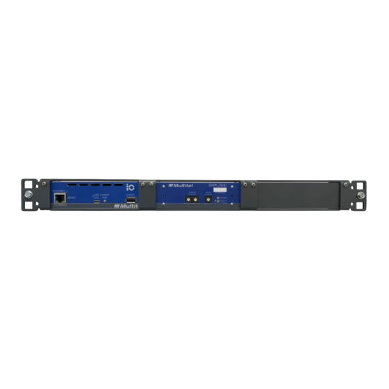
Multitel iO Gateway Installation Manual
Hide thumbs
Also See for iO Gateway:
- Installation manual (45 pages) ,
- User manual (39 pages) ,
- User manual (47 pages)
Summary of Contents for Multitel iO Gateway
- Page 1 IO INSTALLATION GUIDE IO GATEWAY INSTALLATION GUIDE Publication date: June 2020 Author: Simon Boivin, ing. P.Eng. 2020-06-06...
- Page 2 IO INSTALLATION GUIDE CONTROL SHEET Date Issue Description Originator MM/DD/YYYY 06/06/2020 iO Gateway v1.0, v1.1, v1.2 2020-06-06...
-
Page 3: Table Of Contents
HARDWARE INSTALLATION ................. 4 PREPARING TO INSTALL IO GATEWAY ..............4 1.1.1 EQUIPMENT SUPPLIED BY MULTITEL ..............5 1.1.2 REQUIRED TOOLS AND/OR MATERIAL NOT SUPPLIED BY MULTITEL ..... 5 MOUNTING IO GATEWAY..................6 1.2.1 RACK MOUNTING ....................6 1.2.2 STANDALONE ......................6 1.2.3 MOUNTED WITH FUSION .................. -
Page 4: Hardware Installation
RS-485 Maximum Distance will depend on the baud rate. The greater the baud rate is the lower the maximum distance will be. Before proceeding with iO Gateway’s installation it is important to have a good understanding of the possible device relationships and interconnections with third-party smart devices. -
Page 5: Equipment Supplied By Multitel
• Ground cable #14 AWG and ground lugs • Terminal lugs (fork type or others) #22-16 • In-line fuse holders (to protect iO Gateway from signals connected to the shunts or any point other than ground Multitel ordering code: FSBL-TL) •... -
Page 6: Mounting Io Gateway
European and North American relay rack standards and provide a flush installation. The 19" bracket can support up to 3x iO Gateway or SMX Modules. A 4" extension ear is provided for installation on a 23" rack. -
Page 7: Chassis Ground
IO INSTALLATION GUIDE Once the iO Gateway is installed and secured in the rack, the chassis must be connected to a reliable ground source. The ground wire shall be installed in accordance with local electrical safety standards. • For NEC-compliant grounding, a size 14 AWG (22 mm) or larger copper wire and an appropriate user-supplied ring terminal with an inner diameter of 1/4 inch (5 to 7 millimeters) are used for the installation. -
Page 8: Devices Connection To Io Gateway
Gateway comes with two separate Ethernet ports, a 10/100Mbps port is available on the front panel and a 1Gbps port is available on the back panel. iO Gateway can support up to 128x devices with Modbus TCP/IP and in up to 128x devices with SNMP protocol. -
Page 9: Rs-485 Ports Connection
RX “-“ Receive Data – Negative Not Used Not Used iO Gateway can support up to 64 Modbus RTU devices connection on each RS-485 port. The actual limit will depend on the number of data points of each device, and the polling rate. -
Page 10: Figure 6 - Rs-485 Connectors
RS-485 networks should always be wired in a bus (or daisy-chain) configuration. The bus should start at the iO Gateway and then be run to each meter in turn. Branches and “home-run” wiring (i.e. each module is wired back to iO Gateway individually) should be avoided. -
Page 11: Powering Io Gateway
Figure 7 - iO Gateway Power Input 2.1 WIRING POWER INPUT iO Gateway is powered by a continuous -48Vdc power source. The module is equipped with A & B feed positions for power redundancy. Power Input status can be found in the General Parameters –... - Page 12 IO INSTALLATION GUIDE exposed wire from the terminal block plug after the installation. Insert wires into the terminal block according to the following table. Connectors Name Description Type Battery return ground “B” feed BRG - B Battery -48V “B” feed BATT FEED - B Battery return ground “A”...
-
Page 13: Installation Checklist
Are there any loose cables and are all cables attached or tie-wrapped together? Have all mounting screws been tightened? Is the iO Gateway POWER/FAIL LED on the front panel solid green? Are the cable designations clear and self-explanatory? Are the unit IP addressed labeled?


Need help?
Do you have a question about the iO Gateway and is the answer not in the manual?
Questions and answers