Table of Contents
Advertisement
Quick Links
Advertisement
Table of Contents

Related Manuals for Baker Panametrics PanaFlow Z3


Summary of Contents for Baker Panametrics PanaFlow Z3
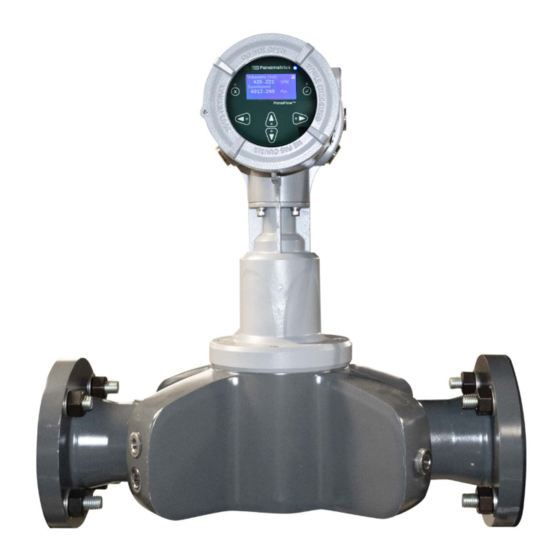
- Page 1 PanaFlow™ Z3 User’s Manual BH026C11 EN E panametrics.com...
- Page 3 March 2024 panametrics.com Copyright 2024 Baker Hughes company. This material contains one or more registered trademarks of Baker Hughes Company and its subsidiaries in one or more countries. All third-party product and company names are trademarks of their respective holders.
- Page 4 [no content intended for this page]...
- Page 5 Preface Services Panametrics provides customers with an experienced staff of customer support personnel ready to respond to technical inquiries, as well as other remote and on-site support needs. To complement our broad portfolio of industry-leading solutions, we offer several types of flexible and scalable support services including: Training, Product Repairs, Service Agreements and more.
- Page 6 Preface Auxiliary Equipment Local Safety Standards The user must make sure that he operates all auxiliary equipment in accordance with local codes, standards, regulations, or laws applicable to safety. Working Area WARNING! Auxiliary equipment may have both manual and automatic modes of operation. As equipment can move suddenly and without warning, do not enter the work cell of this equipment during automatic operation, and do not enter the work envelope of this equipment during manual operation.
-
Page 7: Table Of Contents
Contents Chapter 1. Introduction Overview ......................1 Theory of Operation . - Page 8 Contents Hardware Maintenance and Inspection ............... . 31 5.3.1 Servicing the Pipe Interface .
-
Page 9: Chapter 1. Introduction
Chapter 1. Introduction Chapter 1. Introduction Overview Thank you for purchasing the PanaFlow Z3 ultrasonic flowmeter. The PanaFlow Z3 represents the latest generation of Panametrics ultrasonic flow meters. It is a three-path meter designed specifically for dependable, accurate and repeatable flow measurement of process liquids. With a sleek industrial design and ultra-reliable electronics, it provides operators a cost-effective choice when measurement accuracy and reliability are critical. -
Page 10: Sil Application
Chapter 1. Introduction Figure 3: Transducer Paths Across Flow Directions SIL Application The PanaFlow Z3 with appropriate flow meter selection can be a SIL2 ultrasonic flowmeter (sensor) with the capability of providing a SIL3 system in a redundant design configuration. The PanaFlow Z3 system is IEC61508 certified (when selection) through a complete design validation from a third-party organization. -
Page 11: Chapter 2. Installation
Chapter 2. Installation Chapter 2. Installation Introduction To ensure safe and reliable operation of the PanaFlow Z3, the system must be installed in accordance with the established guidelines. Those guidelines, explained in detail in this chapter, include the following topics: •... -
Page 12: Panaflow Z3 Transmitter Identification
Chapter 2. Installation The PanaFlow Z3 meter has two separate labels for identification, depending on configuration. Transmitter Transmitter Certification Label Tag Plate Tag Plate Model Tag Plate Specification Tag Plate Part String and Serial Number Tag Plate Figure 5: Identification 2.2.1 Panaflow Z3 Transmitter Identification The Panaflow Z3 is supplied with both a serial number label and a certification label for identification of the... -
Page 13: Meter Body Identification
Chapter 2. Installation 2.2.1.1 Meter Body Identification The PanaFlow Z3 meter will have labels for hazardous area, specification, and part string/serial number tag plate. Below are examples of each for reference. Figure 7: Meter body identification 2.2.2 Transport of PanaFlow Z3 Meter Body Below indicates the only approved method to attach the lifting straps to the PanaFlow Z3. -
Page 14: Site Considerations
Chapter 2. Installation Site Considerations Proper installation of the PanaFlow Z3 is important to achieve optimum performance from the system. The following installation recommendations provide general guidelines of how this system should be installed. If the following recommendations cannot be met, please consult the factory for a more detailed review of the application to see what performance may be achievable. -
Page 15: Panaflow Z3 Electronics Mounting & Location
Chapter 2. Installation 2.3.2 Panaflow Z3 Electronics Mounting & Location Typically, the enclosure is mounted as close as possible to the transducers. When choosing a site for remote mount installation, make sure the location permits easy access to the electronics enclosure for programming, maintenance, and service. - Page 16 Chapter 2. Installation Figure 11: Panaflow Z3 Enclosure clearances (ref. dwg. 712-2164) PanaFlow Z3 User’s Manual...
-
Page 17: Making Electrical Connections
Chapter 2. Installation Making Electrical Connections Refer to XMT1000 User Manual for the wiring of: • Analog outputs • Digital outputs (totalizer, frequency, calibration) • Modbus or Service port • Hart or Foundation Field Ports (if applicable) • Additional analog input or output (if applicable) •... - Page 18 Chapter 2. Installation [no content intended for this page] PanaFlow Z3 User’s Manual...
-
Page 19: Chapter 3. Programming
Chapter 3. Programming Chapter 3. Programming Introduction This chapter has instructions for programming various features of the PanaFlow™ Z3 flow transmitter. In this chapter, we will list all available options. The user can then change the User Preferences and Inputs/Outputs settings, Programming for flow measurements and Calibration to meet their needs. -
Page 20: Indicator Lights
Chapter 3. Programming 3.1.2 Indicator Lights • The blue light on the top right above the display is the Power Indicator that is normally lit when the instrument is powered. • The red light on the top left above the display is the Error Indicator. The Error Indicator light blinks if an instrument error is detected. -
Page 21: Changing Display Format
Chapter 3. Programming 3.3.1.1 Changing Display Format To change Display Format, do the following steps and refer Figure 16. Press [] until the lock icon on the meter’s Measurement View display is highlighted, and press [ENTER]. In the Main Menu select [Display Format], then press [ENTER]. Select [One Variable] or [Two Variable] or [Totalizer] format to suit your needs. -
Page 22: Selecting A Composite Measurement To Display
Chapter 3. Programming 3.3.1.2 Selecting a Composite Measurement to Display To select a composite measurement to display on the Measurement View, do the following steps and refer Figure 17. Press [] until the Measurement name on the meter’s Measurement View display is highlighted, and press [ENTER]. -
Page 23: Selecting A Channel Measurement To Display
Chapter 3. Programming 3.3.1.3 Selecting a Channel Measurement to Display To select a Channel measurement to display on the Measurement View, do the following steps and refer Figure 18. Press [] until the Measurement name on the meter’s Measurement View display is highlighted, then press [ENTER]. -
Page 24: Totalizer Display
Chapter 3. Programming 3.3.1.4 Totalizer Display The Totalizer display on the Measurement View shows the totalized measurements and provides the ability to start, stop and reset totals. Refer to Figure 16 to set Display format to Totalizer. Do the following steps to select the appropriate Totalizer measurements to view on the Measurement View. - Page 25 Chapter 3. Programming After completing the log-in steps you will see the primary pages as shown in the Figure 20. To move from one page to the next, press [] or [] and to scroll to options within a page press [] and []. Note: For ease of navigation up and down scroll is circular, meaning if you press [] when the first option is highlighted, then you will be taken to the last option in the page.
-
Page 26: Main Program
Chapter 3. Programming Main Program Please refer to the XMT1000 User’s manual for detailed programming of the XMT1000 Electronics such as System Settings, Inputs/Outputs, Wetted Meter Programming, and Calibration. See chapter “Programming“ for instrument programming step-by-step instructions, or refer to appendix “Menu map” for the full menu map reference guide. PanaFlow Z3 User’s Manual... -
Page 27: Chapter 4. Error Codes And Troubleshooting
Chapter 4. Error Codes and Troubleshooting Chapter 4. Error Codes and Troubleshooting Introduction The PanaFlow Z3 flow transmitter is a reliable, easy to maintain instrument. When properly installed and operated, as described in Chapter: Installation, the meter provides accurate flow rate measurements with minimal user intervention. -
Page 28: Single Channel Error
Chapter 4. Error Codes and Troubleshooting 4.3.1.1 Single Channel Error If only one channel is in error, the most likely causes are: Incorrect programming on Error Limits or flow condition changes that now make previous programming invalid. Defective/Damaged cables, transducers, incorrect physical spacing, couplant, buffer or electronics. After you have tried eliminating/correcting for any most likely causes mentioned above, if error still exists, also check Process/flow conditions such as: Excessive turbulence. - Page 29 Chapter 4. Error Codes and Troubleshooting Table 2: Flow Error description and Recommended Actions Error Code Problem Cause Recommended Action E1: SNR The Signal to Noise The acoustic signal from the Check if the Active Tw measurement ratio is low process is very weak.
-
Page 30: Fluid And Pipe Problems
Chapter 4. Error Codes and Troubleshooting Table 2: Flow Error description and Recommended Actions(Continued) Error Code Problem Cause Recommended Action E6: Cycle Skip A cycle skip is detected This is usually due to poor If this error is caused by changes in while processing the signal integrity, possibly flow rate, this error will be auto... -
Page 31: Fluid Problems
Chapter 4. Error Codes and Troubleshooting • Fluid problems • Pipe problems Read the following sections carefully to determine if the problem is related to the fluid or the pipe. If the instructions in this section fail to resolve the problem, contact Panametrics for assistance. 4.4.1 Fluid Problems Most fluid-related problems result from a failure to observe the flow meter system installation instructions, as... -
Page 32: Transducer Problems
Chapter 4. Error Codes and Troubleshooting 4.5.1 Transducer Problems • Internal Damage: An ultrasonic transducer consists of a ceramic crystal bonded to the transducer case. The bond between the crystal and the case or the crystal itself may be damaged by extreme mechanical shock and/or temperature extremes. - Page 33 Chapter 4. Error Codes and Troubleshooting Table 3: System Error Description and Recommended Actions(Continued) Error Code Error Message Description / Recommended Action Fault: CPU registers have stuck bits. Try power S12: CPU CPU error cycling the meter. If error persists after power cycle, contact Panametrics factory S13: Invariable Flash Flash memory fault...
- Page 34 Chapter 4. Error Codes and Troubleshooting Table 3: System Error Description and Recommended Actions(Continued) Error Code Error Message Description / Recommended Action Fault: SIL Analog Output is disconnected. Connect S29: Output A Loop Open! SIL Analog Output Open Error the SIL Analog output and try power cycling the meter.
-
Page 35: Communication Errors (C-Errors)
Chapter 4. Error Codes and Troubleshooting Communication Errors (C-Errors) The communication error indicates that the Transmitter subsystem has lost communication with Flow measurement sub-system or the Option I/O sub-system. Table 4: Communication Error Description and Recommended Actions Error Code Error Message Description / Recommended Action C1: Flow COMM Error Flow board communication... -
Page 36: Option I/O Errors
Chapter 4. Error Codes and Troubleshooting Option I/O Errors Table 6: Option I/O Errors Description Error Code Error Message Description A1:AnalogCh(S2:3) Error! ADC Channel(S2:3) is not Analog input /RTD input is not working. If error responding persists after power cycle, contact Panametrics factory A2:AnalogCh (S2:4) Error! ADC Channel(S2:4) is not... -
Page 37: 4.10 Diagnostics Data
Chapter 4. Error Codes and Troubleshooting Table 6: Option I/O Errors Description(Continued) Error Code Error Message Description A25:Aout(S2:2)OutOfRan When output from analog Check the flow velocity. If velocity is within limits and output(S2:2) exceeds 21 mA or error still persists, contact Panametrics factory less than 3.6 mA A30:Board Option Err! Optional I/O Error... - Page 38 Chapter 4. Error Codes and Troubleshooting Table 7: Diagnostic Parameter Description and Health Indicators(Continued) Parameter Description Good Gain Up / Gain Gain setting >0 dB and <35 dB >35 dB or <0 dB Down • In water applications, • Gain spreads of 10dB or more under ideal conditions, between the channels can be an gain should be greater...
-
Page 39: Chapter 5. Maintenance And Service
Installation of these field replaceable parts by a Baker Hughes field service team member will maintain the accuracy of the system and any applicable warranty. Please consult Panametrics to order the appropriate components and to schedule installation in the field. -
Page 40: Servicing The Pipe Interface
Chapter 5. Maintenance and Service 5.3.1 Servicing the Pipe Interface WARNING! Before opening the meter body, it must not contain any pressure. Only properly trained personnel (i.e. pipe fitters) should service the pipe flanges. The proper gasket material, nuts, bolts, nut and bolt torque and tightening sequence should always be used. 5.3.2 Servicing the Sensor Ports or Transmitter Interface WARNING! - Page 41 Chapter 5. Maintenance and Service Figure 23: Upstream “A” Plane and “B” Plane Sensor Quadrants – View 1 (Top) Figure 24: Upstream “A” Plane Sensor Quadrant – View 2 (Front) PanaFlow Z3 User’s Manual...
-
Page 42: Instructions To Rotate The Panaflow Z3 Transmitter
Chapter 5. Maintenance and Service Figure 25: Upstream “A” Plane Sensor Quadrant – View 3 (Bottom) 5.3.2.3 Instructions to Rotate the PanaFlow Z3 Transmitter WARNING! All equipment should be de-energized prior to servicing. Before performing any rotation of the PanaFlow Z3 Transmitter, ensure that the enclosure is de-energized. Locate the back of the PanaFlow Z3 Transmitter and remove the rear enclosure cover by turning it counter-clockwise. -
Page 43: Removing The Panaflow Z3 Transmitter
Chapter 5. Maintenance and Service Figure 26: Disassembly Required for PanaFlow Z3 Transmitter Rotation (Back View) 5.3.2.4 Removing the PanaFlow Z3 Transmitter Only properly trained personnel and qualified service technicians should remove the PanaFlow Z3 Transmitter from the flow meter adapter. The PanaFlow Z3 Transmitter contains transducer wiring and sensitive electronics. Modification or alteration in any manner may impact performance of the system. - Page 44 Chapter 5. Maintenance and Service [no content intended for this page] PanaFlow Z3 User’s Manual...
-
Page 45: Appendix A. Specifications
Appendix A. Specifications Appendix A. Specifications Operation and Performance Fluid Types Liquids: acoustically conductive fluids, including most clean liquids, and many liquids with small amounts of entrained solids or gas bubbles. Flow Measurement • Correlation transit time model Accuracy 3 to 24 in (80 to 600 mm) •... - Page 46 Appendix A. Specifications *Maximum process temperature is 203°F (95°C) when additional analog input/output options are selected. Pressure Range Up to maximum allowable flange operating pressure at temperature per ASME B16.5 or EN1092-1 Piping Design ASME B31.3 NACE MR0103/MR0175 PED PER B31.3, CAT II, A2 CRN Weights and Dimensions See Drawings 712-2166 and 712-2167 for details.
-
Page 47: Pressure Derating Information
Appendix A. Specifications Pressure Derating Information ASME B16.5 Figure 27: Pressure derating information as per ASME 16.5 standards PanaFlow Z3 User’s Manual... - Page 48 Appendix A. Specifications EN 1092-1 Figure 28: Pressure derating information as per EN 1092-1 DIN standards PanaFlow Z3 User’s Manual...
-
Page 49: O-Ring Chemical Compatibility
Appendix A. Specifications O-Ring Chemical Compatibility O-rings composed of both EPDM and Viton are used in the Panaflow Z3 flowmeter. Certain process fluids may detriment the performance of these O-rings, therefore impacting the effectiveness and safety of the system overall. Typical applications of O-rings composed of EPDM or Viton: •... - Page 50 PanaFlow Z3 User’s Manual...
- Page 51 PanaFlow Z3 User’s Manual...
- Page 52 PanaFlow Z3 User’s Manual...
- Page 53 PanaFlow Z3 User’s Manual...
- Page 54 PanaFlow Z3 User’s Manual...
- Page 55 PanaFlow Z3 User’s Manual...
-
Page 56: Appendix B. Digital Communications
Appendix B. -Digital Communications Appendix B. -Digital Communications For information on how to communicate using Foundation Fieldbus, Modbus, HART, or Wireless HART, refer to the XMT1000 User Manual appendix section. PanaFlow Z3 User’s Manual... - Page 57 Appendix B. -Digital Communications [no content intended for this page] PanaFlow Z3 User’s Manual...
-
Page 58: Appendix C. Error Code Bit-Field Representation
Appendix C. Error code bit-field representation Appendix C. Error code bit-field representation Table 9: Flow Error Codes in Bit Field Values Error representation Error Description Error code (in Hex) No Error 0x00000000 Velocity Warning 0x00000001 Single Channel Accuracy Error 0x00000002 Multi-Channel Accuracy Error 0x00000004 Active TW Error... - Page 59 Appendix C. Error code bit-field representation Table 10: System Error Codes in Bit Field Values Error representation Error Description Error code (in Hex) Stack overflow 0x00100000 Sequence or Windowed watchdog 0x00200000 failure Initialization failed 0x00400000 DSP Hardware Errors 0x00800000 DSP Exception 0x01000000 Default ISR 0x02000000...
- Page 60 Appendix C. Error code bit-field representation Table 13: Option I/O Errors in Bit Field Values Error representation Error Description Error code (in Hex) No Error 0x00000000 AnalogCh (S2:3) Error! 0x00000001 AnalogCh (S2:4) Error! 0x00000002 AnalogCh (S2:1) Error! 0x00000004 AnalogCh (S2:2) Error! 0x00000008 (S2:3) Ch Not Calibrated 0x00000020...
- Page 61 Appendix C. Error code bit-field representation PanaFlow Z3 User’s Manual...
-
Page 62: Appendix D. Ce Mark Compliance
Appendix D. CE Mark Compliance Appendix D. CE Mark Compliance Introduction For CE Mark compliance, the PanaFlow™ Z3 flow meter must be wired in accordance with the instructions in this appendix. IMPORTANT: CE Mark compliance is required for all units intended for use in EU countries. Wiring The PanaFlow™... - Page 63 Appendix D. CE Mark Compliance [no content intended for this page] PanaFlow Z3 User’s Manual...
- Page 64 Warranty Warranty Each instrument manufactured by Panametrics is warranted to be free from defects in material and workmanship. Liability under this warranty is limited to restoring the instrument to normal operation or replacing the instrument, at the sole discretion of Panametrics. Fuses and batteries are specifically excluded from any liability. This warranty is effective from the date of delivery to the original purchaser.
- Page 65 Warranty [no content intended for this page] PanaFlow Z3 User's Manual...
- Page 67 Copyright 2024 Baker Hughes company. This material contains one or more registered trademarks of Baker Hughes Company and its subsidiaries in one or more countries. All third-party product and company names are trademarks of their respective holders.
Need help?
Do you have a question about the Panametrics PanaFlow Z3 and is the answer not in the manual?
Questions and answers