
Related Manuals for Baker Panametrics CTF878


Summary of Contents for Baker Panametrics CTF878
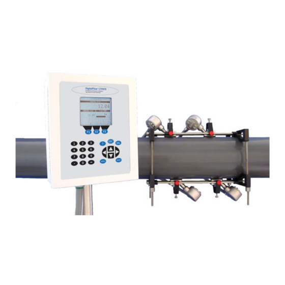
- Page 1 Model CTF878 Clamp-On Tag Flow meter Programming Manual BH010C31 EN C panametrics.com...
- Page 3 May 2023 panametrics.com Copyright 2023 Baker Hughes company. This material contains one or more registered trademarks of Baker Hughes Company and its subsidiaries in one or more countries. All third-party product and company names are trademarks of their respective holders.
- Page 4 [no content intended for this page]...
-
Page 5: Table Of Contents
Contents Chapter 1. Programming Site Data Introduction ..................... . 1 Powering UP . - Page 6 Contents Chapter 5. Logging Data Introduction ....................63 Entering the Logging Menu .
-
Page 7: Chapter 1. Programming Site Data
Chapter 1. Programming Site Data Chapter 1. Programming Site Data Introduction This chapter provides instructions for entering the programming data required to place the CTF878 flowmeter into operation. Before the CTF878 can begin taking measurements and displaying valid data, the current system and pipe parameters must be entered. - Page 8 Chapter 1. Programming Site Data Current Site Measurements Status Bar DEFAULT 2003/07/17 03:35 PM -12.2 12.2 E1: Receiver Example Function Keys System Tray Error Message Figure 2: CTF878 Screen in Operate Mode The top line of the screen is the status bar, which normally displays the time and date. However, when you press [MENU] (the menu key), the menu bar replaces the status line.
-
Page 9: Using The Keypad
Chapter 1. Programming Site Data Using the Keypad The CTF878 keypad contains 24 keys that are labeled with their functions. The complete keypad is illustrated in Figure 3 below and a detailed description of the functions for each of the 24 keys is listed in Table 2 on page 4. CTF878 Flowmeter MENU ENTER... - Page 10 Chapter 1. Programming Site Data Table 2: CTF878 Key Functions Function Software Function Keys: Press to select the special functions displayed directly F1 F2 above them at the bottom of the screen. 12 Numeric Keys: Use to enter numeric data. –...
-
Page 11: Entering The Program Menu
Chapter 1. Programming Site Data Entering the Program Menu To enter the Program Menu, press the [MENU] key at the lower right of the CTF878 keypad. The Menu Bar replaces the Status Bar at the top of the screen. Press the [ ] arrow key once to scroll from the Site Menu to the Program Menu. -
Page 12: Entering Transducer Parameters
Chapter 1. Programming Site Data 1.5.1 Entering Transducer Parameters To enter the Transducer option, scroll to the Transducer tab on the Program Menu and press [ENTER]. The screen appears similar to Figure 5 below. To step through each parameter, press the [ ] key. -
Page 13: Parameters For Typical Transducers
Chapter 1. Programming Site Data Transducer/Pipe * * * WARNING * * * This transducer selection requires a matching Option 3 (1000/888 kHz) Receiver Board. See manual for details. Figure 7: Transducer Selection Warning Screen The Receiver Board option number corresponds to the frequency range selected with the original order (see Table 3 below). -
Page 14: Parameters For Special Transducers
Chapter 1. Programming Site Data 1.5.2 Parameters for Special Transducers Note: The factory will supply the information required below with a special transducer / receiver option. The user must enter the appropriate transducer / receiver operating frequency range. IMPORTANT: The CTF878 flowmeter and the transducers have the same fixed frequency band of operation defined by the customer's application. - Page 15 Chapter 1. Programming Site Data The first prompt asks you to select the pipe material. [ENTER] Press to enter the material prompt. A drop-down list of materials opens as shown in Figure 10 below. Press the [ ] or [ ] keys to scroll to the ...
- Page 16 Chapter 1. Programming Site Data Transducer/Pipe Transducer/Pipe Pipe Pipe Transducer Pipe Fluid Path Material Other Sound Speed 600 m/s OD, mm ODxPI, mm Wall, mm 15.71 English Cancel Figure 11: Pipe Option Window For pipe diameter, two alternatives are available. The meter asks for the pipe outside diameter ( ) and wall Wall thickness (...
-
Page 17: Entering Fluid Types And Speeds
Chapter 1. Programming Site Data Entering Fluid Types and Speeds To access the Fluid option, scroll to the Fluid entry on the Program Menu and press [ENTER]. (If you are already in the Transducer/Pipe form, press the [] arrow key to reach the Fluid window, and press [ENTER].)The screen appears similar to Figure 12 below. -
Page 18: Entering Path Parameters
Chapter 1. Programming Site Data Entering Path Parameters To enter the Path option, scroll to the Path tab on the Program Menu and press [ENTER]. (From the Fluid window, you can scroll back up to the Fluid tab, and press [ENTER].) The screen appears similar to Figure 13 below. To step through each parameter, press the [] key. -
Page 19: Path Parameters For Clamp-On Transducers
Chapter 1. Programming Site Data 1.8.1 Path Parameters for Clamp-On Transducers The CTF878 path menu includes two parameters: • TAG Path • Transducer Spacing The TAG Path is calculated from the data entered in the Pipe parameters under Program. It can be overwritten if the user wants to use a value other than the one calculated by the flowmeter. -
Page 20: Entering Analog Inputs
Chapter 1. Programming Site Data Entering Analog Inputs The Analog Input option enables you to specify parameters for general purpose inputs. To enter the Inputs option, scroll to the Input/Output ( ) entry on the Program Menu and press [ENTER]. The screen appears similar to Figure 15 below. To step through each parameter, press the [] key. - Page 21 Chapter 1. Programming Site Data ENTER Use the [] key and [ ] to select an AnalogIn. At the next prompt, name the input Function by selecting one Off, Pressure Temperature Special of four options: (see Figure 17 below). Note: The units for pressure and temperature are based on the settings in the Meter/Units menu.
- Page 22 Chapter 1. Programming Site Data [ENTER] Press to enter the text box. The text creation window appears, as shown in Figure 19 below. " < > Delete Cancel Figure 19: Text Creation Window Use the four arrow keys to scroll to the desired letter or symbol, and press [ENTER] to add the letter to the name.
-
Page 23: Entering Analog Outputs
Chapter 1. Programming Site Data 1.10 Entering Analog Outputs The Analog Output option enables the set up of additional output parameters. To enter the option, scroll to the Analog Output entry on the Program Menu (see Figure 20 below) and press [ENTER]. Note: Input/Output Menu options may appear in a different order, depending on where each option card is installed. - Page 24 Chapter 1. Programming Site Data The first prompt enables you to select a range to send a current signal to a recording device (see Figure 22 below). [ENTER] Press to open the drop-down menu. Scroll to the desired output from three choices: Off, 0-20 mA, and 4-20 mA. Press [ENTER] to confirm your selection.
- Page 25 Chapter 1. Programming Site Data Select Measurement DIAG Velocity AuxIn Pressure Temperature Volume Fwd Totalizer Rev Totalizer StdFwd Totalizer No Unit Cancel Figure 23: Data Source Selection Window The next prompt requests the span (full scale) value for the analog output. This value represents the 20 mA output (in flow units).
-
Page 26: Entering Digital Outputs
Chapter 1. Programming Site Data 1.11 Entering Digital Outputs While resembling the Analog Output option, the Digital Output option enables you to set up parameters necessary for a digital output. To enter the option, scroll to the Digital Output entry on the Program / IO / Freq/Tot Menu and press [ENTER]. -
Page 27: Entering Alarm Parameters
Chapter 1. Programming Site Data The last set of parameters that appears depends on the selection you made at the Function prompt. Pulse Totalizer If you selected The prompt asks for the units/pulse and the pulse width (in microseconds). (Figure 24 on page 20 illustrates a Digital Output window configured for the Pulse Totalizer function.) For the Units/Pulse and Pulse Width parameters: [ENTER] Press... - Page 28 Chapter 1. Programming Site Data Scroll to the next prompt and select the Data Source measurement type from a list of choices (see Figure 26 below). [ENTER] Press to open the window. Scroll to the desired output type. Press [SEL] to confirm your selection. The prompt then moves to a list of unit types.
-
Page 29: Entering Standard Volume Data
Chapter 1. Programming Site Data 1.13 Entering Standard Volume Data The Standard Volume option enables you to set base measurements and specific values for pressure and temperature inputs and to select the corresponding option cards. To enter this option, scroll to Standard Volume on ENTER the Program Menu and press [ 1.13.1... -
Page 30: Entering Inputs
Chapter 1. Programming Site Data 1.13.2 Entering Inputs Note: You can access the Inputs entry only if you selected Enabled for Standard Volume under the Settings tab. ENTER Use the arrow keys to move to the Inputs tab and press [ ] to confirm your selection. -
Page 31: Entering User Functions
Chapter 1. Programming Site Data To enter a value for the temperature: Press the [] key to move to the Temp box. Press [ENTER] and use the number keys to enter a value for the temperature. Press [ENTER] to confirm your entry. To designate an option card number: Use the arrow keys to move to the Input # box. - Page 32 Chapter 1. Programming Site Data [ENTER] Press to open the text creation window, which appears similar to Figure 30 below. " < > Delete Cancel Figure 30: Text Creation Window Use the four arrow keys to scroll to the desired letter or symbol, and press [ENTER] to add the letter to the label.
-
Page 33: Entering A Calibration Factor
Chapter 1. Programming Site Data sqrt MODE asin acos atan tblA tblB tblC tblD tblE tblF Delete Cancel Figure 31: Function Creation Window To enter a particular measured parameter into the equation, click on the MODE symbol near the middle of the third row. - Page 34 Chapter 1. Programming Site Data Single Table If On is selected for the Calibration Factor, scroll down to choose a K-Factor or a of K-Factors. Use the [ ] and [ ] keys to scroll to the appropriate radio button. Press [ENTER] to confirm your selection.
- Page 35 Chapter 1. Programming Site Data Press the [ ] key to move to the KFactor column. Use the numeric keys to enter the desired value, and press [ENTER] to confirm the entry. 10. Repeat steps 7, 8 and 9 for the remainder of the table. 11.
- Page 36 Chapter 1. Programming Site Data [no content intended for this page] Model CTF878 Programming Manual...
- Page 37 Chapter 1. Programming Site Data Menu Site Meter Logging Service F3 (accept) or Program F2 (not accept) Standard User Correction Transducer Pipe Fluid Path Volume Functions Factors See following figures Tag Path Special Material Txdr Spacing Sound Speed Calibration Settings Inputs Other Factor...
- Page 38 Chapter 1. Programming Site Data Menu Site Meter Logging Service F3 (accept) or Program F2 (not accept) Standard User Correction Transducer Pipe Fluid Path Volume Functions Factors Zero Span Analog Out Data Source On Error 0ma - 20ma Velocity AuxIn Pressure Volume Test...
- Page 39 Chapter 1. Programming Site Data Menu Site Meter Logging Service F3 (accept) or Program F2 (not accept) Std. Volume User Func. Cor. Factors Transducer Pipe Fluid Path Alarms (3) RTDs (4) See previous figure Alarm (3:A) RTD(4:A) Function Function Function Alarm (3:B) RTD(4:B) Frequency...
- Page 40 Chapter 1. Programming Site Data [no content intended for this page] Model CTF878 Programming Manual...
-
Page 41: Chapter 2. Displaying And Configuring Data
Chapter 2. Displaying and Configuring Data Chapter 2. Displaying and Configuring Data Introduction The CTF878 enables the viewing of from one to four different measurement parameters simultaneously. The screen can show these parameters not only in numeric format, but as line or bar graphs as well. You can configure any given measurement for your particular requirements. -
Page 42: View Option
Chapter 2. Displaying and Configuring Data The first entry, Format, asks you to select the numeric format from three choices: default, fixed decimal and scientific. Default provides the default resolution, while Fixed Decimal allows users to override the standard resolution. Scientific format displays the value in mantissa and exponent format. [ENTER] Press to open the drop-down list of format choices. -
Page 43: Measurement Option
Chapter 2. Displaying and Configuring Data The screen appears similar to Figure 40 below. Set Line Graph Parameters Minimum -10000 Maximum 10000 Minutes Use Lines Plot Average Value Show Minimum and Maximum Cancel Figure 40: Line (or Bar) Graph Parameters Window The first prompt asks for the minimum value shown in the graph. -
Page 44: Customizing The Display Screen
Chapter 2. Displaying and Configuring Data Use the [ ] and [ ] arrow keys to reach the desired category of data, and press [SEL]. Then use the [ ] or [ ] arrow keys to select the desired measurement unit (or diagnostic parameter). Press [F3] (OK) to confirm the entry or press [ ] (Cancel) to cancel the changes. -
Page 45: Specifying The Number Of Displayed Parameters
Chapter 2. Displaying and Configuring Data 2.6.1 Specifying the Number of Displayed Parameters As mentioned earlier, the CTF878 can display one to four different measurement parameters simultaneously. However, sometimes you might wish to display only one or two parameters. To change the number of open display ... -
Page 46: Customizing Softkeys
Chapter 2. Displaying and Configuring Data 2.6.2 Customizing Softkeys When the screen is in Operate Mode, you might wish to access a particular submenu frequently without the trouble of scrolling through menus. Customizing the softkeys ([F1], [F2] and [F3]) allows you to access up to three submenus by pressing the associated softkey. -
Page 47: Accessing Meter Data -The About Option
To open the About window, scroll to the About option on the Site Menu and press [ENTER]. The screen appears similar to Figure 47 below. To access data on your specific CTF878, press [F2] (Next). Panametrics CTF Flowmeter Copyright ©2002 Baker Hughes Co. All rights reserved. This product is protected by copyright law and international treaties. - Page 48 Chapter 2. Displaying and Configuring Data [no content intended for this page] Model CTF878 Programming Manual...
-
Page 49: Chapter 3. Creating And Managing Sites
Chapter 3. Creating and Managing Sites Chapter 3. Creating and Managing Sites Introduction As mentioned in Chapter 1, the CTF878 can store site data in files for current and future access. (To learn how to program setup data, refer to Chapter 1, Programming Site Data.) After you answer the necessary questions, simply save the information to a site file. -
Page 50: Site Manager
Chapter 3. Creating and Managing Sites Site Manager To access the Site Manager, press [ ]. Scroll to the Site Menu using the [ ] or [] key. Then press [ENTER]. The MENU drop-down menu appears. At this point, the Site Manager should be highlighted. Press [ENTER] to open the Site Manager window. -
Page 51: Creating A New Site
Chapter 3. Creating and Managing Sites • Saving a Site with a Different Name on page 47 • Refreshing a Site on page 48 • Renaming a Site on page 48 • Deleting a Site on page 49 Arrange files from the Sort submenu (see Figure 59 on page 50.) •... -
Page 52: Opening An Existing Site
Chapter 3. Creating and Managing Sites New Site New Site Site Use the selected site 'SITE03.SIT' as a template? & Figure 52: Template Confirmation Window The meter returns to Operate Mode, with the new site name displayed in the upper left corner of the screen. 3.2.2 Opening an Existing Site If you want to return to a site you have previously saved, first highlight the replacement site in the left window of the... -
Page 53: Saving A Site
Chapter 3. Creating and Managing Sites 3.2.3 Saving a Site You can save the current site in one of two ways: • From the Site Menu, you can scroll down to the Save option and press [ENTER], or • From within the Site Manager, press [MENU] to open the File Menu, scroll to the Save option, and press [ENTER]. In either case, the screen appears similar to Figure 54 below. -
Page 54: Refreshing A Site
Chapter 3. Creating and Managing Sites • Press [F3] (OK) to confirm the entry. The Save Site window then appears. • Press [F2] (No) to cancel saving the site, or • Press [F3] (Yes) to save the site. The CTF878 remains in Site Manager, with the current site saved under both the old and new names. 3.2.5 Refreshing a Site You can refresh a site (updating the display with the most current information) in one of two ways:... -
Page 55: Deleting A Site
Chapter 3. Creating and Managing Sites 3.2.7 Deleting a Site To delete a site in the Site Manager, first highlight that site in the left window of the Site Manager. Then press [MENU] to open the File Menu, scroll to the Delete option, and press [ENTER]. You cannot delete the current (open) site. If you try, the following display appears (see Figure 57 below). -
Page 56: Listing Files By Name
Chapter 3. Creating and Managing Sites 3.2.8 Listing Files by Name If you want to list your files alphabetically by site name within the Site Manager, press [MENU] to open the File Menu. Then press the [] arrow key to scroll to the Sort Menu (see Figure 59 below). Press [ENTER]. The Site Manager screen refreshes, with the sites listed in alphabetical order. - Page 57 Chapter 3. Creating and Managing Sites Figure 60: Site Menu Map Model CTF878 Programming Manual...
- Page 58 Chapter 3. Creating and Managing Sites [no content intended for this page] Model CTF878 Programming Manual...
-
Page 59: Chapter 4. Programming Meter Settings
Chapter 4. Programming Meter Settings Chapter 4. Programming Meter Settings Introduction Along with display formats and site data, CTF878 users can program global settings for the meter that suit their individual preferences. The global settings include: • English or Metric measurement units •... -
Page 60: Selecting Measurement Units
Chapter 4. Programming Meter Settings Selecting Measurement Units The first option, Units, enables you to select either English or Metric units as global measurement units for the CTF878. The selected units then become the default settings for every measurement that has the option for metric/English units. -
Page 61: Changing Date And Time Appearance
Chapter 4. Programming Meter Settings Two alternatives are available to change a highlighted number: • Use the numeric keys to enter the desired number. • Use the [ ] or [ ] arrow keys to scroll, in 1-digit increments, to the desired number. (For example, if the text ... -
Page 62: Adjusting Contrast
Chapter 4. Programming Meter Settings Press [ENTER] to confirm your entry. The CTF878 now asks you to select whether you want the time presented in a 12-hour format (for example, 11:53:23 PM) or in a 24-hour format (23:53:23). [ENTER] Press to open the drop-down menu. -
Page 63: Setting Backlight Timeout
Chapter 4. Programming Meter Settings Setting Backlight Timeout By using the Backlight Timeout option, you can set a specified time that the CTF878 backlight will remain on before turning itself off. To set the backlight timeout: From the Meter menu, scroll to the Backlight entry and press [ENTER]. The Display Options window opens on the Display tab, as shown in Figure 64 on page 56. -
Page 64: Resetting Forward And Reverse Totals
Chapter 4. Programming Meter Settings The program now asks for the baud rate. The default rate is bps. 38400 Note: Although numbers from are available, baud rates higher than are not recommended. 115,200 38,400 [ENTER] Press to open the drop-down menu. ... -
Page 65: 4.10 Setting Up User Tables
Chapter 4. Programming Meter Settings The meter resets the selected total(s) to 0.0 and returns to Operate Mode. 4.10 Setting Up User Tables When you program user functions (see page 25), you can also support them with up to six user tables of non-linear or empirical data. - Page 66 Chapter 4. Programming Meter Settings Note: Pressing [SEL] causes the screen to alternate between a set of upper-case (capital) letters and a set of symbols. Use both screens to create the desired label. Repeat this procedure for each letter or symbol you wish to add to the label (up to a total of fourteen characters).
- Page 67 Chapter 4. Programming Meter Settings Figure 70: Meter Menu Map Model CTF878 Programming Manual...
- Page 68 Chapter 4. Programming Meter Settings [no content intended for this page] Model CTF878 Programming Manual...
-
Page 69: Chapter 5. Logging Data
Chapter 5. Logging Data Chapter 5. Logging Data Introduction A powerful and flexible feature of the CTF878 is data logging. The meter enables you to choose up to 12 parameters to log. You can also select the start time and date, end time and date, and time interval. Logs can run one at a time or simultaneously. -
Page 70: Log Manager
Chapter 5. Logging Data Log Manager The Log Manager offers users a way to check the status and memory size of all the logs currently pending, running or finished. To select Log Manager, scroll to the Log Manager entry on the Logging Menu and press [ENTER]. If no logs have been entered, the screen appears similar to Figure 72 below. -
Page 71: Setting Up A New Log
Chapter 5. Logging Data 5.4.1 Setting up a New Log The New Log option enables you to create and set up parameters for a new log. You can access this option in two ways: • by scrolling to the New Log option in the Logging Menu (as shown in Figure 71 on page 63) and pressing [ENTER], •... - Page 72 Chapter 5. Logging Data Note: A linear log automatically stops when the meter runs out of memory or the specified time is reached. A circular log runs continuously until manually stopped, but only the data from the most recent log cycle is saved.
-
Page 73: Entering Measurements
Chapter 5. Logging Data 5.4.1.2 Entering Measurements Press [ENTER] to open the first entry. The Select Measurement window opens, as shown in Figure 76 below. Select Measurement DIAG Velocity UserFunction AuxIn Pressure Temperature Volume Fwd Totalizer Rev Totalizer No Unit Cancel Figure 76: Select Measurement Window Scroll to the desired output type. -
Page 74: Copying (Cloning) A Selected Log
Chapter 5. Logging Data Logging Site Program Meter Logging Service Volume, m/s Velocity, m/s 10000 -10000 10 Minutes Corr SNR Cross Corr Save Now Figure 78: Operate Mode After New Log Entry 5.4.2 Copying (Cloning) a Selected Log In the Clone Selected Log option, you can copy the parameters of a particular log, modify the parameters, and start the copy. -
Page 75: Deleting A Log
Chapter 5. Logging Data 5.4.4 Deleting a Log To delete a log: First, select the log you wish to delete in the Log Manager (shown in Figure 72 on page 64). Then open the File Menu, scroll to the Delete option, and press [ENTER]. A delete confirmation window opens, as shown in Figure 79 below. -
Page 76: Log Menu
Chapter 5. Logging Data Log Menu The Log Menu allows you to pause, restart or end any or all logs that are currently pending or running. (However, you cannot restart any finished logs, even if they were finished before the programmed end time.) To open the Log Menu in the Log Manager, press [MENU]. -
Page 77: Restarting All Logs
Chapter 5. Logging Data 5.5.5 Restarting All Logs To restart all paused logs, open the Log Menu, scroll to the Start All Logs option, and press [ENTER]. The CTF878 returns to the Log Manager, which displays the logs with a status of “Pending” or “Running.” 5.5.6 Ending All Logs To end all currently pending or running logs, open the Log Menu, scroll to the End All Logs option, and press... -
Page 78: Displaying Log Data In Graphical Form
Chapter 5. Logging Data Log Info State: Finished S:03/01/01 13:13:41 E:03/01/01 13:23:41 Interval: 10 Seconds Records:51 Precision: 8 Error:No (Basic) Velocity:m/s Temperature:Temp C Exit Figure 82: Log Details Display Window Press [F2] (Cancel) or [F3] (OK) to return to the Log Manager. 5.6.2 Displaying Log Data in Graphical Form To view a log in graphical format, be sure the log is highlighted in the left window of the Log Manager. - Page 79 Chapter 5. Logging Data Y-Axis Limits Range Minimum 0.1234 Maximum 0.1234 03/03/01 03/03/01 13:23:41 PM 13:53:41 PM Cancel Figure 84: Y-Axis Window The Y-Axis window (shown in Figure 84 above) allows you to specify whether the Y axis on the graph extends to the maximum value (Max), over the entire range (Range) or between certain specified values (Set).
-
Page 80: Displaying Log Data In Spreadsheet Form
Chapter 5. Logging Data Use the arrow keys to scroll to the desired text box. Press [ENTER] to open the box. Use the numeric keys to enter the desired number. Use the [ ] or [ ] arrow keys to scroll, in 1-digit increments, to the desired number. (For example, if the text box ... -
Page 81: Sort Menu
Chapter 5. Logging Data Sort Menu The Sort Menu within the Log Manager allows you to arrange your log list either alphabetically (By Name) or chronologically (By Date). Log Manager Sort File Log View Sort > By Name 2.LOG LOG02 By Date nished LOG02A... - Page 82 Chapter 5. Logging Data Figure 88: Logging Menu Map Model CTF878 Programming Manual...
- Page 83 Index Locale Option ..........55 About Option .
- Page 84 Index Screen Customizing the Display ....... .38 Description ..........1 Signal Path .
- Page 85 Warranty Warranty Each instrument manufactured by Panametrics is warranted to be free from defects in material and workmanship. Liability under this warranty is limited to restoring the instrument to normal operation or replacing the instrument, at the sole discretion of Panametrics. Fuses and batteries are specifically excluded from any liability. This warranty is effective from the date of delivery to the original purchaser.
- Page 86 Warranty [no content intended for this page] Model CTF878 Programming Manual...
- Page 88 E-mail: panametricstechsupport@bakerhughes.com Copyright 2023 Baker Hughes company. This material contains one or more registered trademarks of Baker Hughes Company and its subsidiaries in one or more countries. All third-party product and company names are trademarks of their respective holders. BH010C31 EN C (05/2023)
Need help?
Do you have a question about the Panametrics CTF878 and is the answer not in the manual?
Questions and answers