Table of Contents
Advertisement
Quick Links
Advertisement
Table of Contents
Troubleshooting

Subscribe to Our Youtube Channel
Related Manuals for Baker Panametrics PanaFlow LC


Summary of Contents for Baker Panametrics PanaFlow LC
- Page 1 PanaFlow™ LC User’s Manual BH029C11 EN C panametrics.com...
- Page 3 March 2024 panametrics.com Copyright 2024 Baker Hughes company. This material contains one or more registered trademarks of Baker Hughes Company and its subsidiaries in one or more countries. All third-party product and company names are trademarks of their respective holders.
- Page 4 [no content intended for this page]...
- Page 5 Preface Services Panametrics provides customers with an experienced staff of customer support personnel ready to respond to technical inquiries, as well as other remote and on-site support needs. To complement our broad portfolio of industry-leading solutions, we offer several types of flexible and scalable support services including: Training, Product Repairs, Service Agreements and more.
- Page 6 Preface Auxiliary Equipment Local Safety Standards The user must make sure that he operates all auxiliary equipment in accordance with local codes, standards, regulations, or laws applicable to safety. Working Area WARNING! Auxiliary equipment may have both manual and automatic modes of operation. As equipment can move suddenly and without warning, do not enter the work cell of this equipment during automatic operation, and do not enter the work envelope of this equipment during manual operation.
-
Page 7: Table Of Contents
Contents Chapter 1. Introduction Overview ......................1 Theory of Operation . - Page 8 Contents Transmitter Errors ....................40 Option I/O Errors .
-
Page 9: Chapter 1. Introduction
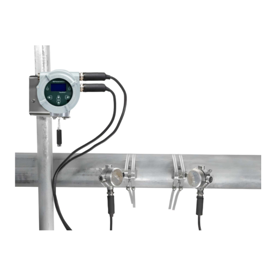
Chapter 1. Introduction Chapter 1. Introduction Overview Thank you for purchasing the PanaFlow LC ultrasonic flowmeter. The PanaFlow LC flowmeter is a one, two, or three channel ultrasonic transit time flowmeter that utilizes clamp on transducers on external pipe surfaces to allow for uninterrupted flow operation during flow measurement. -
Page 10: Theory Of Operation
Chapter 1. Introduction Theory of Operation The PanaFlow LC uses a procedure called Transit-Time Flow Measurement. In this method, the flowmeter transmits ultrasonic pulses through a moving liquid. The pulses that travel in the same direction as the fluid flow (downstream) travel slightly faster than the pulses that travel against the fluid flow (upstream). -
Page 11: Chapter 2. Installation
Chapter 2. Installation Chapter 2. Installation Installation Guidelines This section provides general information with respect to the mechanical and electrical installation, and should be thoroughly reviewed before the system is installed. To ensure safe and reliable operation of the PanaFlow LC, the system must be installed in accordance with the established guidelines. -
Page 12: Unpacking
Chapter 2. Installation Unpacking Before removing the PanaFlow LC from its box, please inspect both the box and the instrument carefully. Each instrument manufactured by Panametrics is warranted to be free from defects in material and workmanship. Before discarding any of the packing materials, account for all components and documentation listed on the packing slip. The discarding of an important item along with the packing materials is all too common. -
Page 13: Site Considerations
Chapter 2. Installation Site Considerations Proper installation of the PanaFlow LC is important to achieve optimum performance from the system. The following installation recommendations provide general guidelines of how this system should be installed. If the following recommendations cannot be met, please consult the factory for a more detailed review of the application to see what performance may be achievable. - Page 14 Chapter 2. Installation Figure 4: Recommended Installation Location and Orientation • If the clamping fixture is to be placed downstream of an elbow, the orientation of the clamping fixture must be placed in such a way that the transducer path is perpendicular to the plane of the piping to compensate for swirl.
-
Page 15: Installing Clamping Fixtures
Chapter 2. Installation Installing Clamping Fixtures Installation of clamp-on transducers for transit-time measurements consists of mounting the clamping fixture to the Installation of clamp-on transducers for transit-time measurements consists of mounting the clamping fixture to the pipe and then mounting the transducers into the clamping fixture. When installing transducers in clamp-on applications, you can use one of the following methods to hold the transducer against the pipe wall (this manual will only cover the SCF and V-Series clamping fixture): •... -
Page 16: Determining Transducer Spacing
Chapter 2. Installation 2.4.2 Determining Transducer Spacing Transducer spacing is determined by programming the PanaFlow LC transmitter with process conditions as described in the programming menu section of the XMT1000 manual. Final spacing will be determined by the pipe specification, fluid, transducers, and traverses. Please refer to the XMT1000 manual determining transducer spacing. For installation of SCF Fixture, please go to Section 2.4.3. -
Page 17: Install Of Scf Fixture (Even Traverses)
Chapter 2. Installation 2.4.3.1 Install of SCF Fixture (Even Traverses) Note: The instructions in this section can also be used for a multiple-traverse method. However, you must use an EVEN number of traverses. The distance the signal travels from one side of the pipe wall to the opposite side of the pipe wall is considered one traverse. -
Page 18: Install Of Scf Fixture (Odd Traverses)
Chapter 2. Installation Figure 8 below shows a completed even-traverse installation without the transducers. Proceed to the section on mounting the transducers later in this chapter. Figure 8: Finished SCF Installation without Transducers 2.4.3.2 Install of SCF Fixture (Odd Traverses) Note: The instructions in this section can also be used for a multiple-traverse method. - Page 19 Chapter 2. Installation Figure 10: SCF Odd Number of Traverse Installation, Step 4 From one of the marks on the top of the pipe, measure around the pipe a distance equal to 1/4 of the pipe circumference, or a distance that will satisfy the orientation found in Step 1. Use the center punch to make a mark at this point.
- Page 20 Chapter 2. Installation Figure 13: SCF Odd Number of Traverse Installation, Step 7 Repeat Step 7 to install the other block on the pipe. IMPORTANT: Make sure both straps are perpendicular to the bottom of the block. If the straps are slanted, the slack will cause the block to move.
-
Page 21: Installation Of Transducer
Chapter 2. Installation Figure 15: Odd Number of Traverse SCF Installation without Transducer 2.4.3.3 Installation of Transducer For any of the fixtures above except for the SPCF, the last step in the installation is mounting the transducers into the clamping fixture. Although not all transducer models are installed the same way, the following information provides some general guidelines to help you. - Page 22 Chapter 2. Installation To mount the transducers into a clamping fixture, complete the following steps: To ensure that the minimum bend radius of the cable is met, the cable adapter is added in series with the transducer cable assembly and the transducer. Connect the transducer cables to the BNC connectors on the transducers, ensuring that the labels on the cables match with the transducers.
- Page 23 Chapter 2. Installation Figure 19: Transducer Mounting, Step 2 Panametrics supplies an ultrasonic couplant for your clamp-on installation. The purpose of the couplant is to provide reliable transmission of ultrasound between two adjacent solid surfaces. Couplants perform this task by excluding air from the space between the adjacent surfaces.
- Page 24 Chapter 2. Installation Determine the upstream and downstream ends of the pipe and place the appropriate transducer into the corresponding block on one of the sub-assemblies. Make sure the transducer cable connector faces away from the center of the installation. Figure 20: Transducer Mounting on UCF (Top Left), MCF (Top Right), GCF (Bottom Left), and SCF (Bottom Right) Use the pressure bolt to secure the transducer in place.
-
Page 25: Installation Of Cfg Fixture
Chapter 2. Installation Figure 21: SCF Clamping Fixture (Top Left), UCF Clamping Fixture (Top Right), GCF Clamping Fixture (Bottom Left), MCF Clamping Fixture (Bottom Right) 2.4.4 Installation of CFG fixture To install the V Series clamping fixture and transducers, complete the following steps: 2.4.4.1 Installing the Fixture Position the half of the clamping fixture with the threaded rods around the pipe, as shown in Figure 22 below. - Page 26 Chapter 2. Installation Position the mating half of the fixture over the threaded rods in the 9 o’clock position. Figure 22 below shows the two mounted halves. Figure 22: Mounting the Two Halves of the Fixture The two fixture halves have measuring scales; ensure that the scales are on the same side of the fixture, so that both zeros start at the same origin, as shown in Figure 23 below.
-
Page 27: Installing The Transducers
Chapter 2. Installation Install the four nuts onto the threaded rods with the convex side of the nut facing the fixture. Hand tighten the nuts on each V block evenly, as shown in Figure 24 on the next page. Do not use a cross tightening pattern on the four installation nuts. - Page 28 Chapter 2. Installation Slide the second mounting block to the calculated spacing plus the initial scale number selected for the first mounting block. (For example: Initial convenient number for the first mounting block = 5 cm or 2 in. Spacing as calculated by the GC868 = 0.5 in. or 12.5 mm Second mounting block final location = 2 + 0.5 in.
-
Page 29: Electronic Enclosure Accessibility
Chapter 2. Installation Electronic enclosure accessibility Typically, the enclosure is mounted as close as possible to the transducers. When choosing a site for remote mount installation, make sure the location permits easy access to the electronics enclosure for programming, maintenance, and service. -
Page 30: Wiring Instructions
Chapter 2. Installation Wiring instructions Please refer to the XMT1000 User Manual for wiring of: • Analog outputs • Digital outputs (totalizer, frequency, calibration) • Modbus or Service port • Hart or Foundation Field Ports (if applicable) • Additional analog input or output (if applicable) •... - Page 31 Chapter 2. Installation Thread one end of transducer cables into 3 channel junction box as shown in Figure 30. (Cable locations in Figure 30 are for reference only. Transducer cables can be placed in any orientation) Figure 30: XMT1000, 3 Channel Junction Box Thread CH1 UP transducer cable into upstream junction box of the transducer set you will use for channel one.
- Page 32 Chapter 2. Installation [no content intended for this page] Figure 31: XMT1000 3-Channel Backplane PanaFlow™ LC User’s Manual...
-
Page 33: Chapter 3. Programming
Chapter 3. Programming Chapter 3. Programming Introduction This chapter has instructions for programming various features of the PanaFlow LC flow transmitter. In this chapter, we will list all available options. The user can then change the User Preferences and Inputs/Outputs settings, Programming for flow measurements and Calibration to meet their needs. -
Page 34: Indicator Lights
Chapter 3. Programming 3.1.2 Indicator Lights • The blue light on the top right above the display is the Power Indicator that is normally lit when the instrument is powered. • The red light on the top left above the display is the Error Indicator. The Error Indicator light blinks if an instrument error is detected. -
Page 35: Changing Display Format
Chapter 3. Programming 3.3.1.1 Changing Display Format To change Display Format, do the following steps and refer Figure 34. Press [] until the lock icon on the meter’s Measurement View display is highlighted, and press [ENTER]. In the Main Menu select [Display Format], then press [ENTER]. Select [One Variable] or [Two Variable] or [Totalizer] format to suit your needs. -
Page 36: Selecting A Composite Measurement To Display
Chapter 3. Programming 3.3.1.2 Selecting a Composite Measurement to Display To select a composite measurement to display on the Measurement View, do the following steps and refer Figure 35. Press [] until the Measurement name on the meter’s Measurement View display is highlighted, and press [ENTER]. -
Page 37: Selecting A Channel Measurement To Display
Chapter 3. Programming 3.3.1.3 Selecting a Channel Measurement to Display To select a Channel measurement to display on the Measurement View, do the following steps and refer Figure 36. Press [] until the Measurement name on the meter’s Measurement View display is highlighted, then press [ENTER]. -
Page 38: Totalizer Display
Chapter 3. Programming 3.3.1.4 Totalizer Display The Totalizer display on the Measurement View shows the totalized measurements and provides the ability to start, stop and reset totals. Refer to Figure 34 to set Display format to Totalizer. Do the following steps to select the appropriate Totalizer measurements to view on the Measurement View. - Page 39 Chapter 3. Programming After completing the log-in steps you will see the primary pages as shown in the Figure 38. To move from one page to the next, press [] or [] and to scroll to options within a page press [] and []. Note: For ease of navigation up and down scroll is circular, meaning if you press [] when the first option is highlighted, then you will be taken to the last option in the page.
-
Page 40: Main Program
Chapter 3. Programming Main Program Please refer to the XMT1000 User manual for detailed programming of the XMT1000 Electronics such as System Settings, Inputs/Outputs, Wetted Meter Programming, and Calibration. See chapter “Programming“ for instrument programming step-by-step instructions, or refer to appendix “Menu map” for the full menu map reference guide. PanaFlow™... -
Page 41: Chapter 4. Error Codes And Troubleshooting
Chapter 4. Error Codes and Troubleshooting Chapter 4. Error Codes and Troubleshooting Introduction The XMT1000 flow transmitter is a reliable, easy to maintain instrument. When properly installed and operated, as described in Chapter: Installation, the meter provides accurate flow rate measurements with minimal user intervention. -
Page 42: Flow Errors (E-Errors)
Chapter 4. Error Codes and Troubleshooting Flow Errors (E-Errors) 4.3.1 General Guidelines for Troubleshooting Flow Errors with Error codes If the Error code on the LCD or Vitality PC software indicate E22: SingleChAccuracy or E23: MultiChAccuracy, refer to the appropriate section below. Also, refer to Table 3 below for causes and recommended actions for each Error code. 4.3.1.1 Single Channel Error If only one channel is in error, the most likely causes are:... - Page 43 Chapter 4. Error Codes and Troubleshooting Table 3: Flow Error description and Recommended Actions Error Code Problem Cause Recommended Action E1: SNR The Signal to Noise The acoustic signal from the Check if the Active Tw measurement ratio is low process is very weak.
- Page 44 Chapter 4. Error Codes and Troubleshooting Table 3: Flow Error description and Recommended Actions Error Code Problem Cause Recommended Action E6: Cycle Skip A cycle skip is detected This is usually due to poor If this error is caused by changes in while processing the signal integrity, possibly flow rate, this error will be auto...
-
Page 45: Fluid And Pipe Problems
Chapter 4. Error Codes and Troubleshooting Fluid and Pipe Problems If preliminary troubleshooting with the Error Code Messages and the Diagnostic Parameters indicates a possible problem, proceed with this section. Measurement problems fall into two categories: • Fluid problems • Pipe problems Read the following sections carefully to determine if the problem is related to the fluid or the pipe. -
Page 46: Transducer Problems
Chapter 4. Error Codes and Troubleshooting Transducer Problems Ultrasonic transducers are rugged, reliable devices. However, they are subject to physical damage from mishandling and chemical attack. The following list of potential problems is grouped according to transducer type. Contact Panametrics if you cannot solve a transducer-related problem. 4.5.1 Transducer Problems •... - Page 47 Chapter 4. Error Codes and Troubleshooting Table 4: System Error Description and Recommended Actions Error Code Error Message Description / Recommended Action Fault: Input clock frequency failure. Try power S11: Clock Frequency Clock frequency error cycling the meter. If error persists after power cycle, contact Panametrics factory S12: CPU CPU error...
-
Page 48: Communication Errors (C-Errors)
Chapter 4. Error Codes and Troubleshooting Table 4: System Error Description and Recommended Actions Error Code Error Message Description / Recommended Action Fault: SIL Analog Output is disconnected. Connect S29: Output A Loop Open! SIL Analog Output Open Error the SIL Analog output and try power cycling the meter. -
Page 49: Option I/O Errors
Chapter 4. Error Codes and Troubleshooting Table 6: Transmitter Error Description and Recommended Actions Error Code Error Message Description / Recommended Action X15: Font API Initialize Fail Failed to generate font Failed to generate font. Try power cycling the meter. If error persists after power cycle, contact Panametrics factory X16: XML File Initialize Fail... -
Page 50: 4.10 Diagnostics Data
Chapter 4. Error Codes and Troubleshooting Table 7: Option I/O Errors Description Error Code Error Message Description A11:(S2:4)Input Analog Input: Error occurs when Check connectivity for Analog Input/RTD input and NotConnect! (4-20mA) input is not RTD temperature. Try power cycling the meter. If connected at Channel (S2:4). - Page 51 Chapter 4. Error Codes and Troubleshooting To determine the health of the meter, PanaFlow™ LC has built-in diagnostic parameters. Please refer to Table 8 below for diagnosing any problems with the system. If the meter shows errors and the diagnostics data indicate issues, fill in the User/Service record appendix before contacting Panametrics factory.
- Page 52 Chapter 4. Error Codes and Troubleshooting Table 8: Diagnostic Parameter Description and Health Indicators Parameter Description Good Peak Index Down Threshold peak of the • For pipe sizes greater • For pipe sizes greater than 1 inch, if downstream transmit than 1 inch, index should the index <400 or >700 then there correlation signal...
-
Page 53: Chapter 5. Maintenance And Service
Installation of these field replaceable parts by a Baker Hughes field service team member will maintain the accuracy of the system and any applicable warranty. Please consult Panametrics to order the appropriate components and to schedule installation in the field. - Page 54 Chapter 5. Maintenance and Service [no content intended for this page] PanaFlow™ LC User’s Manual...
-
Page 55: Appendix A. Specifications And Model Configurations
Appendix A. Specifications and Model Configurations Appendix A. Specifications and Model Configurations Operation and Performance Fluid Types Liquids: acoustically conductive fluids, including most clean liquids, and many liquids with small amounts of entrained solids or gas bubbles. Maximum void fraction depends on transducer, interrogation carrier frequency, path length, and pipe configuration. - Page 56 Appendix A. Specifications and Model Configurations [no content intended for this page] PanaFlow™ LC User’s Manual...
-
Page 57: Appendix B. Digital Communication
Appendix B. Digital Communication Appendix B. Digital Communication For information on how to communicate using Foundation Fieldbus, Modbus, HART, or Wireless HART, refer the XMT1000 User Manual. PanaFlow™ LC User’s Manual... - Page 58 Appendix B. Digital Communication [no content intended for this page] PanaFlow™ LC User’s Manual...
-
Page 59: Appendix C. Error Code Bit-Field Representation
Appendix C. Error code bit-field representation Appendix C. Error code bit-field representation Table 9: Flow Error Codes in Bit Field Values Error representation Error Description Error code (in Hex) No Error 0x00000000 Velocity Warning 0x00000001 Single Channel Accuracy Error 0x00000002 Multi-Channel Accuracy Error 0x00000004 Active TW Error... - Page 60 Appendix C. Error code bit-field representation Table 10: System Error Codes in Bit Field Values Error representation Error Description Error code (in Hex) Stack overflow 0x00100000 Sequence or Windowed watchdog 0x00200000 failure Initialization failed 0x00400000 DSP Hardware Errors 0x00800000 DSP Exception 0x01000000 Default ISR 0x02000000...
- Page 61 Appendix C. Error code bit-field representation Table 13: Option I/O Errors in Bit Field Values Error representation Error Description Error code (in Hex) No Error 0x00000000 AnalogCh (S2:3) Error! 0x00000001 AnalogCh (S2:4) Error! 0x00000002 AnalogCh (S2:1) Error! 0x00000004 AnalogCh (S2:2) Error! 0x00000008 (S2:3) Ch Not Calibrated 0x00000020...
- Page 62 Appendix C. Error code bit-field representation [no content intended for this page] PanaFlow™ LC User’s Manual...
-
Page 63: Appendix D. Ce Mark Compliance
Appendix D. CE Mark Compliance Appendix D. CE Mark Compliance Introduction For CE Mark compliance, the PanaFlow LC flow meter must be wired in accordance with the instructions in this appendix. IMPORTANT: CE Mark compliance is required for all units intended for use in EU countries. Wiring The PanaFlow LC must be wired with the recommended cable, and all connections must be properly shielded and grounded. - Page 64 Appendix D. CE Mark Compliance [no content intended for this page] PanaFlow™ LC User’s Manual...
- Page 65 Warranty Warranty Each instrument manufactured by Panametrics is warranted to be free from defects in material and workmanship. Liability under this warranty is limited to restoring the instrument to normal operation or replacing the instrument, at the sole discretion of Panametrics. Fuses and batteries are specifically excluded from any liability. This warranty is effective from the date of delivery to the original purchaser.
- Page 66 Warranty [no content intended for this page] PanaFlow LZ User's Manual...
- Page 68 Copyright 2024 Baker Hughes company. This material contains one or more registered trademarks of Baker Hughes Company and its subsidiaries in one or more countries. All third-party product and company names are trademarks of their respective holders.
Need help?
Do you have a question about the Panametrics PanaFlow LC and is the answer not in the manual?
Questions and answers