Advertisement
Quick Links
Manufacturer:
Dunster House Ltd.
Caxton Road
Bedford
Bedfordshire
England
MK41 0LF
Customer Service department:
cs@dunsterhouse.co.uk
www.dunsterhouse.co.uk
Packed with PS626
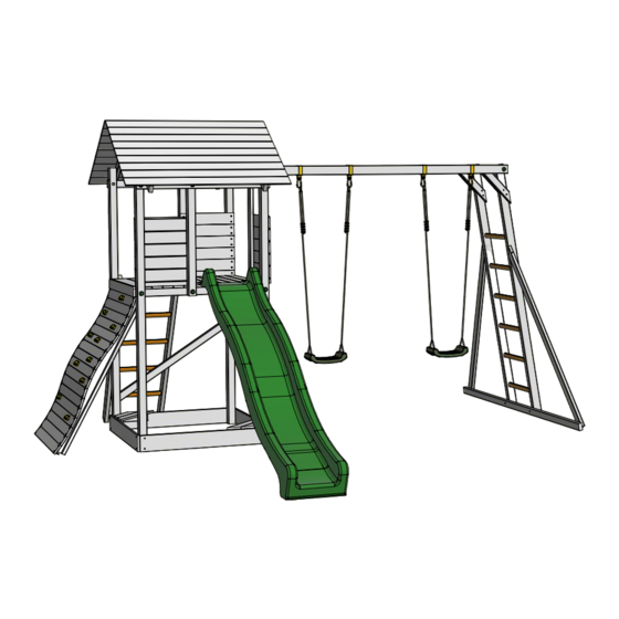
Installation Manual
MaxiFort Frontier II
PS626
Hammer
Ladder
for
Two adults (and tools) are required for assembly.
Socket
wrench
Tape
measure
Screwdriver
Cordless drill/drill
Spirit level
Advertisement

Subscribe to Our Youtube Channel
Related Manuals for Dunster House MaxiFort Frontier II


Summary of Contents for Dunster House MaxiFort Frontier II
- Page 1 Installation Manual MaxiFort Frontier II Manufacturer: Dunster House Ltd. Caxton Road PS626 Bedford Bedfordshire England MK41 0LF Customer Service department: cs@dunsterhouse.co.uk Two adults (and tools) are required for assembly. www.dunsterhouse.co.uk Spirit level Tape Hammer measure Ladder Socket wrench Screwdriver Packed with PS626...
- Page 2 Fax: (01234) 224497 Post: Dunster House Ltd., Caxton Road, Elms Farm Industrial Estate, Bedford MK41 0LF, England. Our Customer Service department is open 9 a.m. - 5 p.m. Monday to Friday and aim to respond within 2-3 hours of receipt, however, this may be longer during busy periods. Please include your Sales Order (SO) number in any correspondence with Customer Services to enable them to locate your file.
- Page 3 Bolt Configuration Please use this page to ensure that the fixings for your play system are installed correctly. You must use these claw washers in every location where you are instructed to use an M10 (10mm diameter) bolt. These pronged washers create a sleeve for the square ‘neck’...
- Page 4 Maintenance for MaxiFort Frontier II Maintenance of the MaxiFort Frontier II is very important and should be carried out at the beginning of each season as well as at regular intervals during usage to ensure the Fort remains safe. Failure to carry out these checks could cause the Fort to overturn or become a hazard.
- Page 5 Maintenance for MaxiFort Frontier II Please retain these instructions for future reference. Components (Sizes in mm) 8 of M10x155mm coach bolt, 4 of Ground anchor square shoulder 1 of M10x145mm coach bolt, 1 of 8mm drill bit square shoulder 4 of...
-
Page 6: Step 1 - Required Components
Assembly Instructions for MaxiFort Frontier II This play system is intended for family domestic use and for outdoor use only. This toy is suitable for children aged between 3-14 years and up to a maximum weight of 50Kg per child and a maximum of 5 children at any time, but only 2 children can play on the tower platform. - Page 7 Assembly Instructions for MaxiFort Frontier II Step 2 - required components 2 of C40314A - 70x70x2490 3 of M10x155mm bolt, 6 of M10x20mm washer, 3 of M10 nut, 3 of Green 10mm cap, 1 of C4070A - 70x70x1015 3 Claw washer...
- Page 8 Assembly Instructions for MaxiFort Frontier II Step 4 - required components 2 of C4048A - 70x35x1375 8 of 5x70mm countersunk screw C4048A - 70x35x1375 C4048A - 70x35x1375 5x70mm countersunk screws Step 5 - required components 22 of 4.5x35mm countersunk screw...
- Page 9 Assembly Instructions for MaxiFort Frontier II Step 6 - required components 5 of C4038A - 44x44x550 - rungs 2 of C4076A - 86x43x1680 20 of 4x50mm countersunk screw Lay the items on the ground first C4038A - 44x44x550 - rungs...
- Page 10 Assembly Instructions for MaxiFort Frontier II Step 8 - required components 1 of C4093A - 86x86x2600 2 of C40306A - 86x43x2530 52 of 4x50mm 4 of Swing hook 1 of C4031A - 86x43x2600 countersunk screw 13 of C4038A - 44x44x550 - rungs 4 of 4.5x35mm...
- Page 11 Assembly Instructions for MaxiFort Frontier II Step 9 - required components Vertical ladder 2 of C4035A - 70x35x385 2 of C4034A - 70x35x415 1 of M10x145mm 1 of M10x100mm 14 of 5x70mm Horizontal monkey bar assembly coach bolt, 2 of...
- Page 12 Assembly Instructions for MaxiFort Frontier II 5x70mm countersunk screws C4035A - 70x35x385 4.8x95mm countersunk screw 5x70mm countersunk screws 5x70mm countersunk screw C4035A - 70x35x385 4.8x95mm countersunk screw Step 10 - required components 5x70mm countersunk screw 2 of L-bracket 16 of 4.5x35mm...
- Page 13 Assembly Instructions for MaxiFort Frontier II Step 11 - required components 2 of C4036A - 70x35x1950 4 of 5x70mm countersunk screw 2 of 4.8x95mm 1 of C4037A - 70x35x2600 countersunk screw 4.8x95mm countersunk screw 4.8x95mm countersunk screw 5x70mm countersunk screws...
- Page 14 Assembly Instructions for MaxiFort Frontier II Step 13 - required components 8 of 5x70mm Roof (Step 12) countersunk screw Lift up and position the roof panel between the tower legs. Secure the roof panel in position using 2 of 5x70mm countersunk screws per tower leg.
- Page 15 Assembly Instructions for MaxiFort Frontier II Step 15 - required components 2 of climbing wall support legs 17 of C4069A - 90x19x1055 66 of 4x50mm countersunk screw 4x50mm countersunk screw C4069A - 90x19x1055 climbing wall support legs climbing wall support legs Position all boards with a maximum gap of 1mm between each one.
- Page 16 Assembly Instructions for MaxiFort Frontier II Step 17 - required components 4 of 5x70mm countersunk screw 1 of Climbing wall 5x70mm countersunk screws View from underneath the platform Climbing wall Step 18 - required components 1 of C40100A - 90x19x1055...
- Page 17 Step 18 - required components 4 of M10x70mm hex head screw, 4 of Ground anchor 2 of Swing seat 1 of Slide 4 of M10x30mm washer 2 of 5x70mm countersunk screw To fix the slide to the platform, lift the slide onto the platform and position it so that it is central on the platform and doesn't stick out from the platform edge.
- Page 18 Slide Care Advice / Maintenance To ensure that you enjoy the maximum usage of your slide, please take note of and follow the maintenance/advice contained on this page. You MUST install the slide as per the installation instructions in the location it is intended to go. You CANNOT install the slide in any other location on the platform otherwise any warranty claims will be rendered void.
Need help?
Do you have a question about the MaxiFort Frontier II and is the answer not in the manual?
Questions and answers