
Related Manuals for Simpson 42142


Summary of Contents for Simpson 42142
- Page 1 Operating Instructions Electronic Mold Hardness Tester Model 42142 Model 42143 www.simpsongroup.com...
- Page 2 Simpson Technologies Corporation or its subsidiaries which shall not be disclosed outside or duplicated, used or disclosed in whole or in part for any purpose other than to evaluate Simpson Technologies for a proposed transaction. Any use or disclosure in whole or in part of this information without the express written permission of Simpson Technologies Corporation is prohibited.
-
Page 3: Table Of Contents
Working Modes Screen Description..........15 5.3.1 Basic Model .................... 15 5.3.2 Advanced Model ..................17 5.3.3 Store Data Into Tester Memory .............. 18 5.3.4 Point Mode - Advanced Model ..............18 5.3.5 Average Mode - Advanced Model ............19 man-stc-42142-42143-V17-2 Electronic Mold Hardness Tester... - Page 4 Warranty, Service, Calibration and Support ....... 31 7 Parts List / Ordering Parts / Returns .........32 Spare Parts List ................32 Ordering Replacement / Spare Parts .......... 32 Returned Goods Policy ..............32 8 Decommissioning...............34 Electronic Mold Hardness Tester man-stc-42142-42143-V17-22...
-
Page 5: Introduction 1
This laboratory equipment is constructed of quality materials and is the result of unsurpassed craftsmanship. The Electronic Mold Hardness Tester (Model 42142-42143) should be operated only when it is in perfect condition, in accordance with its designed purpose and being aware of possible hazards. Observe the safety instructions in Section 2 and operating instructions in Section 5. -
Page 6: Safety
This symbol indicates information containing important instructions concerning the use of the machine or directions for further procedures. Ignoring this information can lead to malfunction of the machine. Electronic Mold Hardness Tester man-stc-42142-42143-V17-22... - Page 7 Improperly using the battery can cause it to leak and damage nearby items and may cause the risk of fire or personal injury. We reserve the right to all modifications which do not affect the technical content of these Operating Instructions. man-stc-42142-42143-V17-2 Electronic Mold Hardness Tester...
-
Page 8: Short Description & Specifications
Basic point to point mode » Auto average mode » Scan mode » Store up to 900 data points » Identify up to 32 molds » Digital calibration of displacement » Infrared data transfer to computer Electronic Mold Hardness Tester man-stc-42142-42143-V17-22... -
Page 9: Modes Of Operation
This information can be gathered and displayed as gradient lines by plotting the depth vs. hardness numbers. The scan information can also be stored in memory and downloaded to a computer. man-stc-42142-42143-V17-2 Electronic Mold Hardness Tester... -
Page 10: Specifications
3 Short Description & Specifications Specifications Requirements Electronic Mold Hardness Tester (42142/42143) Power AAA Rechargeable NiMH Battery (Battery Charger not included) Software Windows Excel Software (ADV Models Only) Dimensions and Weights (Approximate) Dimensions/Weights Electronic Mold Hardness Tester (42142/42143) Length 102 mm (4 in.) Width 64 mm (2.5 in.) -
Page 11: Unpacking And Installation
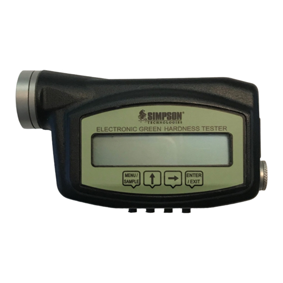
Failure to follow this instruction may nullify any claims under warranty. The basic model should have the following: (See Figure 1) » Electronic Mold Hardness Tester Unit (0042142/00142143) » AAA Battery (Ni-MH rechargeable is included) » Holster Figure 1: Model 42142 & 42143 man-stc-42142-42143-V17-2 Electronic Mold Hardness Tester... - Page 12 AAA Battery (Ni-MH rechargeable is included) » Infrared receiver assembly; including receiver, and USB cable » Calibration assembly, including mount and micrometer and Aluminum foot » Holster » Aligning Allen wrench Figure 2: Model 42142ADV & 42143ADV Electronic Mold Hardness Tester man-stc-42142-42143-V17-22...
-
Page 13: Preparation - Battery Status
0042142ADV & 0042143ADV 1. Insert supplied USB thumb drive into your computer’s USB port and copy the file Simpson eLab x86 x64 r1 to a convenient location on your hard drive. If you wish, you can make a shortcut Icon on your desktop for quick access. - Page 14 5. Assemble the cord (Figure 4). The “USB” connector plugs into the USB port of the PC. Position the IR receiver facing to the Infrared Data Port from the Tester. Figure 4: USB Cable and Infrared IR Receiver Electronic Mold Hardness Tester man-stc-42142-42143-V17-22...
-
Page 15: Operating Instructions
Operating Instructions 5 Operating Instructions For more information on how to use and care for your Simpson Analytics equipment and accessories visit our Simpson Technologies channel on YouTube and search our library of videos. Subscribe to our channel to keep updated on new releases. - Page 16 5 Operating Instructions • Refer to Figures 5-7 for location of the various components while following this instruction manual: Figure 5 Item Description Penetrator MENU Button UP Button RIGHT Button ENTER Button LCD Screen Electronic Mold Hardness Tester man-stc-42142-42143-V17-22...
- Page 17 Operating Instructions 5 Figure 6 Item Description Battery Compartment Infrared Data Port Covered Spring Port (DO NOT REMOVE RUBBER COVER) Figure 7: Penetrator (1) Penetrator Face (2) and Body (3) man-stc-42142-42143-V17-2 Electronic Mold Hardness Tester...
-
Page 18: Type "B" And "C" Scale Description
Type “B” and “C” Scale Description There are two types of scale for measuring mold hardness. Model 42142 is the B-Scale (round penetrator) measuring; Model 42143 is the C-scale (pointed penetrator). Both scales measure the surface hardness of the mold by penetration. The difference between the two depends on the load and on the shape of the penetrator (see Figure 8). -
Page 19: Working Modes Screen Description
In the upper left corner of the display is the letters Md, this repre- sents 'mode'. The starting mode is Point (see Figure 10). You may cycle through modes by pressing the <UP> button when the cursor is under the 'P' (see Figure 10). man-stc-42142-42143-V17-2 Electronic Mold Hardness Tester... - Page 20 LCD should return to Md. Refer to Section 5.4 User Information Screens for instructions on setting the clock or go to Section 5.5 for information on changing other options. Electronic Mold Hardness Tester man-stc-42142-42143-V17-22...
-
Page 21: Advanced Model
This mode is useful in determining the change in mold hardness, for instance in a deep mold pocket. » Link: Allows the user to transfer the memory to the computer. » Read: Only shows the displacement of the penetrator. man-stc-42142-42143-V17-2 Electronic Mold Hardness Tester... -
Page 22: Store Data Into Tester Memory
Press <ENTER> button to start the work mode. The Md should change to Wk (work mode), indicating that the unit is ready to take read- ings (see Figure 15). The Point mode automatically holds the maximum value of hardness displacement. Electronic Mold Hardness Tester man-stc-42142-42143-V17-22... -
Page 23: Average Mode - Advanced Model
It also shows the ‘n’ (number of readings taken). Like Point, it shows the maximum hardness displacement for the average (see Figure 16). Press the unit down until the penetrator face is just touching the surface of the mold. man-stc-42142-42143-V17-2 Electronic Mold Hardness Tester... -
Page 24: Scan Mode - Advanced Model
Press the unit down until the penetrator face is just touching the surface of the mold. DO NOT FORCE the penetrator face into the mold, as this will make the results inaccurate (see Figure 12). Record the reading in the lower right corner of the display. Electronic Mold Hardness Tester man-stc-42142-42143-V17-22... -
Page 25: Link Mode - Advanced Model
<MENU> button (Figure 5, Item 2), make sure the unit is positioned in line with the infrared receiver (tester end facing the IR receiver), (See Figure 19). Keep the unit in this position until all of the data is transferred. man-stc-42142-42143-V17-2 Electronic Mold Hardness Tester... -
Page 26: User Information Screens
This screen shows the current user name (see Figure 21). The only function available in this screen is a key combination to enter the SETUP MODE, see the section on Setup Screens)(see Section 5.5, Figure 25). Electronic Mold Hardness Tester man-stc-42142-42143-V17-22... -
Page 27: Current Scale Type Screen Description
The <UP> button will increment the number, and the <RIGHT> button will advance the cursor position. To exit the editing mode, simply press <ENTER> button again. Pressing <MENU> button will return you to work mode screen. man-stc-42142-42143-V17-2 Electronic Mold Hardness Tester... -
Page 28: Setup Description
To change the characters, press <UP> button. The characters will increment by one character in a cyclical fashion. To increment backward, press <MENU> button. This will advance in the reverse direction in a cyclical fashion. Electronic Mold Hardness Tester man-stc-42142-42143-V17-22... -
Page 29: Editing Mold Identification Name
To increment backwards, press <MENU> button. This will advance in the reverse direction in a cyclical fashion. Once you enter the complete name, press <ENTER> button again to quit. Pressing <MENU> button will change to next screen. man-stc-42142-42143-V17-2 Electronic Mold Hardness Tester... -
Page 30: Setting Calibration Points
The process requires that you set seven points. Figure 31 After you have installed the hardness tester into the calibration device and have the calibration screen on, you are ready to set the first point. Electronic Mold Hardness Tester man-stc-42142-42143-V17-22... - Page 31 Once the micrometer is set, press <MENU> button to store the first point. This is the zero reference. The screen will change to set the second point, 0.5mm (see Figure 33). Turn the micrometer one whole turn from the first micrometer reading, this is 0.5мм. man-stc-42142-42143-V17-2 Electronic Mold Hardness Tester...
-
Page 32: Timer And Battery Status
ASTO is the number of the minimum reading before the timer is activated. Increase the value by pressing the <UP> button. Decrease the value by pressing the <RIGHT> button. There is one decimal point in the number; example: 0200 is 20.0. This is your minimum reading. Electronic Mold Hardness Tester man-stc-42142-42143-V17-22... -
Page 33: Viewing Memory Status - Setup Description
To exit the SETUP MODE, you must cycle through all of the setup screens. After you have reached the memory screen, pressing <MENU> button once more will get the screen out of setup and to the User Name screen and the instrument will return to normal operation. man-stc-42142-42143-V17-2 Electronic Mold Hardness Tester... -
Page 34: Maintenance And Calibration
6 Maintenance and Calibration Maintenance and Calibration For more information on how to use and care for your Simpson Analytics equipment and accessories visit our Simpson Technologies channel on YouTube and search our library of videos. Subscribe to our channel to keep updated on new releases. -
Page 35: Warranty, Service, Calibration And Support
Warranty does not cover calibration. Simpson Technolo- gies reserves the right to decide the conditions under which this warranty is void. Visit our website at www.simpsongroup.com. If there are problems or if you have questions, call Simpson Technologies Corporation. back... -
Page 36: Parts List / Ordering Parts / Returns
7 Parts List / Ordering Parts / Returns Parts List / Ordering Parts / Returns Spare Parts List Simpson maintains a large inventory of common spare parts for all current Simpson Analytics products. Contact Simpson Technologies with the part number and description when ordering. - Page 37 (subject to a restocking charge). • A Safety Data Sheet (SDS) must accompany material that is sent to Simpson Technologies Corporation for testing purposes. Simpson Technologies Corporation will NOT authorize the return of hazardous materials. RETURN PROCEDURE: • The customer must obtain a Return Material Authorization Number (RMA#) from Simpson Technologies prior to returning the goods.
-
Page 38: Decommissioning
Hardness Tester Model. The instrument consists of: • Steel • Aluminum • Copper • Plastic • Electronic Components and circuit boards • AAA Battery (Ni-MH Rechargeable) Dispose of the parts in accordance with the applicable regulations. Electronic Mold Hardness Tester man-stc-42142-42143-V17-22... - Page 39 Decommissioning 8 This Page Is Intentionally Blank. man-stc-42142-42143-V17-2 Electronic Mold Hardness Tester...
- Page 40 Fax: +91 (33) 2290 8050 simpsongroup.com Copyright 2021. All rights reserved. SIMPSON, the illustrative logo and all other trademarks indicated as such herein are registered trademarks of Simpson Technologies Corporation. For illustrative purposes the Simpson equipment may be shown without any warning labels and with some of the protective devices removed. The warning labels and guards must always be in place when the equipment is in use.
Need help?
Do you have a question about the 42142 and is the answer not in the manual?
Questions and answers