
Related Manuals for THEORY sb25aw


Summary of Contents for THEORY sb25aw
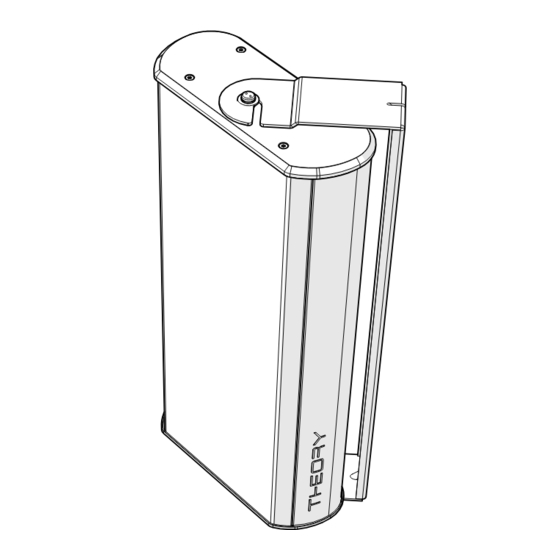
- Page 1 Multi-use Loudspeaker QUICK START INSTALLATION GUIDE Rev A 230824 Theory sb25aw QUICK START...
-
Page 2: Limited Warranty
LIMITED WARRANTY Disclaimer : THEORY AUDIO DESIGN, LLC is not liable for any damage to loudspeakers or any other equipment that is caused by negligence or improper use or installation of this product, including damage caused by connecting Theory loudspeakers and subwoofers to third party ampli- fiers. -
Page 3: Important Safety Instructions
Do not install near any heat sources such as radiators, heat registers, stoves or other apparatus that produce heat. Use only attachments/accessories specified by THEORY AUDIO DESIGN, LLC. Use only with hardware, brackets, stands, and components sold with the apparatus or supplied by THEORY AUDIO DESIGN, LLC. 10. Mount only to solid architectural walls. -
Page 4: Product Features
OPERATING MODES - SAFETY CONSIDERATIONS - INDOOR/OUTDOOR INSTALLATIONS Your Theory sb25aw loudspeaker can be used in LoZ (4-ohms) or HiZ (transformer) operating modes. Make sure you know the desired operation for your system prior to installing the loudspeakers as this will determine the wiring scheme required. -
Page 5: Installation Options
FLAT, PAN-AND-TILT, YOKE, POLE Your Theory sb25aw Multi-use loudspeaker can be installed in many different ways, making integration into even challenging interiors painless. Below is a list of installation options available. Before you begin your project, review the options and select the method that best suits your project. - Page 6 1d. - POLE MOUNT - YOKE (THEORY sb25aw-YOKE SOLD SEPARATELY) The sb25aw may be mounted to a 1/2” rigid conduit pole using the optional sb25aw-YOKE mounting bracket, as shown. The speaker cable(s) and safety tether(s) may be routed through the conduit for a clean appearance.
- Page 7 1 - INSTALLATION OPTIONS (cont’d) 1e. - POLE MOUNT - PAN AND TILT BRACKET (BRACKET SOLD SEPARATELY) The sb25aw may be mounted to a 1/2” rigid conduit pole using the optional MM-018 mounting bracket, as shown. Pole mount model MM-018 shown.
- Page 8 3 - SAFETY TETHER TIE POINTS 3a. SAFETY TIE POINTS On the rear of the sb25aw loudspeaker there are many con- nection points that can be used to connect a safety tether. Any of the screws highlighed red in Figure 3a. may be used.
- Page 9 FIGURE 3c. Main sb25aw safety tie point. 3d. POLE MOUNT - YOKE (THEORY sb25aw-YOKE SOLD SEPARATELY) When using the sb25aw-YOKE mounting bracket to suspend the loudspeaker from a pole, the safety cable configuration shown in Figure 3d. should be used. One or more safety cables may be used.
- Page 10 4c. MOUNT LOUDSPEAKER Once wires are connected and checked for polarity, position the sb25aw such that the loudspeaker Z-CLIP is tight against the wall surface and directly above the wall Z-CLIP. (Figure 4d.) Slowly lower the loudspeaker until the speaker Z-CLIP engages completely into the wall Z-CLIP.
- Page 11 5b. INSTALL TAMPER-RESISTANT BOLT AND WASHERS INTO ONE END OF LOUDSPEAKER LOCK WASHER To make it possible for one person to install the sb25aw FLAT WASHER loudpseaker into the sb25aw-YOKE mount bracket, one end of the yoke features a slot, and the other end a thru hole. The “slot”...
- Page 12 QUICK START GUIDE - sb25aw 5 - WALL MOUNT - YOKE (cont’d) 5d. HAND-TIGHTEN SPANNER SCREW Once screw is fully inserted into yoke slot, hand-tighten the screw to hold it in the slot so that you can install the spanner screw at the other end of the yoke.
- Page 13 Remove the Euro input plug from the socket. Peel off the adhesive backer from included foam gastket and adhere it to the recessed surface surrounding the terminal socket on the sb25aw back panel as shown. (Figure 6a.) FIGURE 6a. Adhere the supplied gasket into loudpseaker back panel recess as shown.
- Page 14 7b. INSTALL CONDUIT (NOT INCLUDED). 3/8” NPT conduit or conduit adapters may now be screwed into the sb25aw terminal cover’ s 3/8” threaded opening. Figure 7b. FIGURE 7b. 3/8” NPT conduit or conduit adapters may be screwd directly into the terminal cover’...
-
Page 15: Specifications
© 2023 THEORY AUDIO DESIGN, LLC. All rights reserved. Theory Audio Design routinely engages in programs to improve, modify and revise its products without notice or obligation. As such, your product may differ slightly from what is shown in this guide.
Need help?
Do you have a question about the sb25aw and is the answer not in the manual?
Questions and answers