Table of Contents
Advertisement
Available languages
Available languages
Quick Links
EN
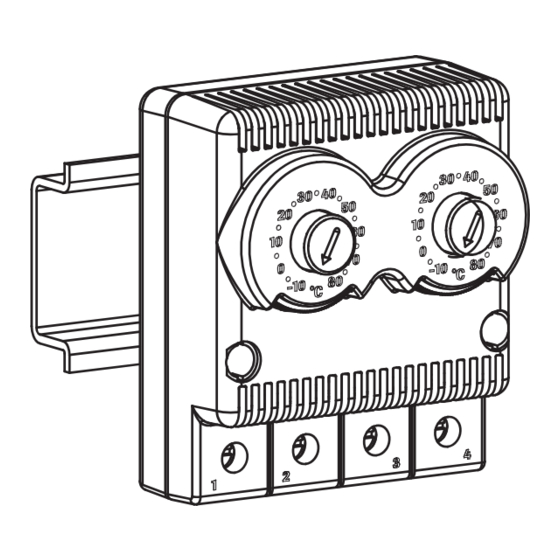
Dual thermostat
EF-TER2 series
EF-TER2 series
SGANCIO
SGANCIO
AGGANCIO
I N S T A L L A T I O N
2
2
2
Hook the thermostat on the rail using the proper elastic hooks.
1
2
Connect the thermostat electrically (see Electrical Connections).
1
1
1
3
Adjust the set point temperature by rotatingthe graduated discs.
1
RAIL MOUNTING
To avoid damage to the elastic fixing elements of the thermostat, follow the
instructions alongside.
IO
AGGANCIO
ASSEMBLY
2
1
ELECTRICAL CONNECTIONS
The dual thermostat is provided with four screw terminals for external conductors
with cross-section from 0.75 mm
The terminals have capacity for two wires each in order to allow connection of
many devices to the same thermostat.
To connect the thermostat, follow these instructions:
• use flexible conductors suitable for the terminals provided
• loosen each terminal screw and insert the conductor, then tighten the screws.
When finished, pull the conductors gently to verify if they are tight enough
• to tighten the screws, do not exceed 0.5 Nm torque
WIRING DIAGRAMS
Heater
N
L
All specifications, data and drawings are subject to change without notice.
EN - Multilingual manual
PL - Instrukcja wielojęzyczna
SI - Večjezični priročnik
DE - Mehrsprachiges Handbuch
AGGANCIO
AGGANCIO
2
2
1
1
2
3
+
SGANCIO
DISASSEMBLY
2
1
to 2.5 mm
.
2
2
NC - NO
(red - blue)
Cooler
UA - Багатомовний посібник
LT - Daugiakalbis vadovas
LV - Daudzvalodu rokasgrāmata
CZ - Vícejazyčný manuál
OPERATION
The NO dual thermostat (blue) has open contact when the temperature is below the set
point value and closes with rising temperatures.
Fig.1 shows the typical operation cycle: the contact closes with rising temperature, at
the value T=T set point +4K when the rated current is 5A, or T=T set point +7K when
the rated current is > 5A.
The contact opens on descent at the value T=T set point . The set point value represents
the lower limit of the setting temperature range, the upper limit represents the differential,
having a value of +4K or +7K with respect to the set point value.
The NC dual thermostat (red) has closed contact when the temperature is below the
set point value and opens with rising temperatures.
Fig. 2 shows the typical operation cycle: the contact opens with rising temperature, at the
value T=T set point and closes on descent at the value T=T set point -3K. The set point
value represents the upper limit of the setting temperature range, the lower limit represents
NO
{
the differential, having a value of -3K with respect to the set point value.
T
BETWEEN
T
NO
{
T
BETWEEN
T
-
+
+
NC
NC
Setting temperature range:
Differential
AGGANCIO
(ref.: set point):
rail
35x7.5mm
Accuracy:
rail
Rated voltage:
2
35x15mm
Rated current:
Max rated current:
1
DIN 46 277/3
Endurance:
EN 50 022
Degree of protection by enclosure:
Electrical connection:
Protection against shock:
Applicable standard:
Method of mounting:
+
Enclosure material:
External dimensions:
Weight:
Mounting suggestions
The thermostat must not be mounted in environments with the following
characteristics:
• presence of strong vibrations or impacts
• environmental conditions not met by IP20 protection
• exposure to direct sun rays
• heat or cold sources
• openings or ventilation slots which allow the passage of hot or cold air
WARNING
This device should be installed inside enclosure. Any use different from this and any modifications,
not expressly authorized by the manufacturer, are considered inappropriate. Eventual damages
due to an inappropriate use are the full responsibility of the user.
All the service and maintenance operations must be carried out by qualified personnel only in
compliance with the respective EU power-supply guidelines.
The protective measures and the protection against contact are to be ensured by the
installation. The thermostat is a live device, reactive to the ambient temperature. Before installing
or following work on the thermostat or attached devices, disconnect from the electrical supply.
N
L
The assembly instructions are an integral part of the product. They must be issued to everyone
who works with the product. We cannot accept any liability for damage associated with failure to
observe these instructions.
SK - Viacjazyčný manuál
HR - Višejezični priručnik
T (°C )
+4K
set point
+7K
set point
T
T (°C )
set point
+4K
set point
+7K
OPEN
CLOSED
set point
T
set point
OPEN
CLOSED
-
-
T (°C)
T
set point
T (°C)
T
-3K
set point
T
set point
CLOSED
OPEN
T
-3K
set point
CLOSED
OPEN
TECHNICAL SPECIFICATIONS
from -10°C to +80°C
-3K for NC (red)
+4K for NO (blue) rated current ≤ 5A
+7K for NO (blue) rated current > 5A
± 3 K
12 - 60 V d.c.
terminals 1-2: 10A (AC1) 122W (AC3)
terminals 3-4: 10A (AC1) 122W (AC3)
15A
> 100,000 cycles
IP20
4 screw terminals for each 2 conductors
sizes from 0.75mm
class II (double insulation)
EN 60730-1
-
rail-fixing: DIN 46 277 type 3
PA 66 UL94V-0
58x72.5x44.5mm
0.14Kg
ETI, d.o.o., Obrezija 5, SI-1411 Izlake
FIG. 1
FIG. 1
OPEN
CLOSED
OPEN
time
OPEN
CLOSED
OPEN
time
FIG. 2
FIG. 2
CLOSED
OPEN
CLOSED
time
CLOSED
OPEN
CLOSED
time
110 - 250 V a.c.
to 2.5mm
2
2
-
+
www.etigroup.eu
Advertisement
Table of Contents

Related Manuals for ETI EF-TER2 Series


Summary of Contents for ETI EF-TER2 Series
- Page 1 UA - Багатомовний посібник SK - Viacjazyčný manuál PL - Instrukcja wielojęzyczna LT - Daugiakalbis vadovas HR - Višejezični priručnik SI - Večjezični priročnik LV - Daudzvalodu rokasgrāmata DE - Mehrsprachiges Handbuch CZ - Vícejazyčný manuál www.etigroup.eu ETI, d.o.o., Obrezija 5, SI-1411 Izlake...
-
Page 2: Połączenia Elektryczne
UA - Багатомовний посібник SK - Viacjazyčný manuál PL - Instrukcja wielojęzyczna LT - Daugiakalbis vadovas HR - Višejezični priručnik SI - Večjezični priročnik LV - Daudzvalodu rokasgrāmata DE - Mehrsprachiges Handbuch CZ - Vícejazyčný manuál www.etigroup.eu ETI, d.o.o., Obrezija 5, SI-1411 Izlake... - Page 3 UA - Багатомовний посібник SK - Viacjazyčný manuál PL - Instrukcja wielojęzyczna LT - Daugiakalbis vadovas HR - Višejezični priručnik SI - Večjezični priročnik LV - Daudzvalodu rokasgrāmata DE - Mehrsprachiges Handbuch CZ - Vícejazyčný manuál www.etigroup.eu ETI, d.o.o., Obrezija 5, SI-1411 Izlake...
-
Page 4: Elektrischer Anschluss
UA - Багатомовний посібник SK - Viacjazyčný manuál PL - Instrukcja wielojęzyczna LT - Daugiakalbis vadovas HR - Višejezični priručnik SI - Večjezični priročnik LV - Daudzvalodu rokasgrāmata DE - Mehrsprachiges Handbuch CZ - Vícejazyčný manuál www.etigroup.eu ETI, d.o.o., Obrezija 5, SI-1411 Izlake... -
Page 5: Електричні Підключення
UA - Багатомовний посібник SK - Viacjazyčný manuál PL - Instrukcja wielojęzyczna LT - Daugiakalbis vadovas HR - Višejezični priručnik SI - Večjezični priročnik LV - Daudzvalodu rokasgrāmata DE - Mehrsprachiges Handbuch CZ - Vícejazyčný manuál www.etigroup.eu ETI, d.o.o., Obrezija 5, SI-1411 Izlake... -
Page 6: Elektros Jungtys
UA - Багатомовний посібник SK - Viacjazyčný manuál PL - Instrukcja wielojęzyczna LT - Daugiakalbis vadovas HR - Višejezični priručnik SI - Večjezični priročnik LV - Daudzvalodu rokasgrāmata DE - Mehrsprachiges Handbuch CZ - Vícejazyčný manuál www.etigroup.eu ETI, d.o.o., Obrezija 5, SI-1411 Izlake... - Page 7 UA - Багатомовний посібник SK - Viacjazyčný manuál PL - Instrukcja wielojęzyczna LT - Daugiakalbis vadovas HR - Višejezični priručnik SI - Večjezični priročnik LV - Daudzvalodu rokasgrāmata DE - Mehrsprachiges Handbuch CZ - Vícejazyčný manuál www.etigroup.eu ETI, d.o.o., Obrezija 5, SI-1411 Izlake...
-
Page 8: Elektrické Připojení
UA - Багатомовний посібник SK - Viacjazyčný manuál PL - Instrukcja wielojęzyczna LT - Daugiakalbis vadovas HR - Višejezični priručnik SI - Večjezični priročnik LV - Daudzvalodu rokasgrāmata DE - Mehrsprachiges Handbuch CZ - Vícejazyčný manuál www.etigroup.eu ETI, d.o.o., Obrezija 5, SI-1411 Izlake... -
Page 9: Elektrické Pripojenie
UA - Багатомовний посібник SK - Viacjazyčný manuál PL - Instrukcja wielojęzyczna LT - Daugiakalbis vadovas HR - Višejezični priručnik SI - Večjezični priročnik LV - Daudzvalodu rokasgrāmata DE - Mehrsprachiges Handbuch CZ - Vícejazyčný manuál www.etigroup.eu ETI, d.o.o., Obrezija 5, SI-1411 Izlake... - Page 10 UA - Багатомовний посібник SK - Viacjazyčný manuál PL - Instrukcja wielojęzyczna LT - Daugiakalbis vadovas HR - Višejezični priručnik SI - Večjezični priročnik LV - Daudzvalodu rokasgrāmata DE - Mehrsprachiges Handbuch CZ - Vícejazyčný manuál www.etigroup.eu ETI, d.o.o., Obrezija 5, SI-1411 Izlake...
Need help?
Do you have a question about the EF-TER2 Series and is the answer not in the manual?
Questions and answers