Table of Contents
Advertisement
Quick Links
TRACON
®
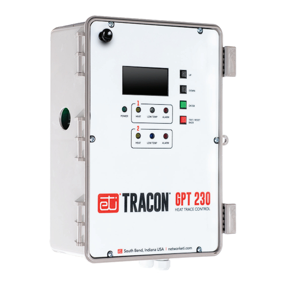
MODEL GPT-230
DUAL–POINT HEAT–TRACE CONTROL THERMOSTAT
TABLE OF CONTENTS
GPT 230 Overview ................................................................................... 2
Installation ................................................................................................ 3
Power Source and Load Connections................................................... 4
Temperature Sensor Installation ............................................................ 5
Panel Lockout and External Alarm ........................................................ 6
Operation ................................................................................................. 6
Controls and Screens .............................................................................. 9
Settings Screen Viewing/Editing Setting ............................................ 10
Specifications ......................................................................................... 11
Pilot Duty
The GPT 230 General Purpose Thermostat with GFEP cannot be used
for Pilot Duty applications.
Resistive Load Usage Only
This product is not for use with Inductive loads. Inductive loads
may create nuisance tripping of the Ground–Fault Equipment
Protection circuit.
Abnormal Odor or Smoke
In the event of smoke or a burning or abnormal odor, immediately
interrupt power to the unit by turning off the circuit breaker protecting
the unit.
Electrical Shock / Fire Hazard
Any installation involving electric heater wiring must be grounded
to earth to protect against shock and fire hazard. Suitable ground
fault detection and interrupting systems must be in use at all times to
reduce shock and fire hazard and to protect equipment.
Electric wiring to heating elements must be installed in accordance
with National Electrical Code (NEC)/Canadian Electrical Code
requirements, as well as all other local and applicable electrical
codes and any thirdparty standards. This product is intended for
commercial and industrial applications. Follow the installation
South Bend, Indiana USA
|
networketi.com
GPT-230 INSTALLATION MANUAL | PART NO.
25167
REV
C.1
Advertisement
Table of Contents

Related Manuals for ETI Tracon GPT 230


Summary of Contents for ETI Tracon GPT 230
- Page 1 TRACON ® MODEL GPT-230 DUAL–POINT HEAT–TRACE CONTROL THERMOSTAT TABLE OF CONTENTS GPT 230 Overview ................... 2 Installation ....................3 Power Source and Load Connections........... 4 Temperature Sensor Installation ............5 Panel Lockout and External Alarm ............6 Operation ....................6 Controls and Screens ................
-
Page 2: Installation
• Adjustable alarm thresholds for excess ground fault OVERVIEW current, load current, and temperature The TRACON GPT 230 Dual Channel Heat–Trace Control • Alarms indicated with panel display and relay contact is a dual–point microprocessor–based heat–trace control for remote signaling thermostat. - Page 3 The GPT 230 is permanently connected equipment and FIGURE 1. The GPT 130 wiring layout does not have an internal disconnect device. The installer must provide an accessible disconnect device, with short circuit and overcurrent protection (these are not supplied by Environmental Technology Inc). When power is applied, the system will start.
-
Page 4: Operation
Contactor Ratings POWER SOURCE AND CONTACTOR CONNECTIONS The heater contactor provides two (2) Form A (DPST) Supply Voltage contacts rated for heater loads up to 30 A ac and 277 V ac. The GPT 230 operates from 100 – 277 V ac at 50/60 These two contacts are used to control both legs of the Hz. - Page 5 TEMPERATURE SENSOR The unit can use RTD sensors for applications requiring Each channel of the GPT 230 can use either a thermistor a wider temperature range. The GPT 230 can operate (provided), or a 2–,3–, or 4–wire RTD sensor. When using with 2–, 3–, or 4–wire RTD sensors.
- Page 6 The heater will de-energize when the temperature meets the designated High Temperature. The GPT 230 features ETI’s patented self–testing GFEP, which switches the system off when it detects excessiveground current leakage. The GFEP eliminates the extra expenses associated with having to provide an external GFEP.
-
Page 7: Controls And Screens
Power Fail. Critical alarms always turn off the heat, unless Fire Protect Mode is ON. To continue normal operation, any of these will require a manual reset. The manual reset (TEST/RESET BACK pushbutton) will start a self test, and if all Critical Alarms are cleared then normal operation will resume. - Page 8 – On settings menus this pushbutton backs out of an Temperature Display screen – Indicates the current operation without changing anything. temperature in Fahrenheit or Celsius. This screen will also show any associated alarm conditions. – Energizes heater for system testing or troubleshooting. Pressing this pushbutton for five seconds while on Load Current Display screen –...
-
Page 9: Settings Screen Viewing/Editing Setting
Multi-field Screen Editing GPT 230 SETTINGS SCREEN VIEWING/EDITING SETTINGS In screens that display multiple fields, there are two SETTINGS SCREENS columns. The left column displays the name of the To enter the Settings sequence press the ENTER parameter, and the right column displays the current pushbutton while in the Settings screen. - Page 10 SETTING SCREENS Note: Screens with a number “1” in the upper right corner indicate that these settings are for Channel 1. There is a second set of these screens for Channel 2 which have a “2” in the upper right hand corner. The Channel 2 Settings screens will follow the Channel 1 Settings screens in the Settings sequence.
-
Page 11: Specifications
SPECIFICATIONS General User Interfaces Certifications UL 60730–1, UL 1053, Pushbuttons UP, DOWN, ENTER, TEST / RESET CSA E60730–1:13 BACK Environmental DIP switches RTD wiring configuration Panel lockout Area of use Nonhazardous locations Remote Interface Operating temperature range −40 °F to 122 °F (−40 °C to 50 °C) Alarm relay Isolated SPDT 1 AMP Class 2 Enclosure... - Page 12 For assistance, contact Customer Service. Office hours are changes and improvements to the products described from 8:00 AM until 5:00 PM ET. in this publication, without the obligation of ETI to notify Email: info@networketi.com any person or organization of such revisions, changes or improvements.
Need help?
Do you have a question about the Tracon GPT 230 and is the answer not in the manual?
Questions and answers