
Subscribe to Our Youtube Channel
Related Manuals for Pendulum CNT-104S


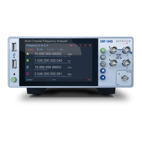
Summary of Contents for Pendulum CNT-104S
- Page 1 CNT-104S U S E R M A N U A L Part No.: 12NC 4031.601.10401 Revision: Date: 09.07.2023 © 2023 Pendulum Instruments. All rights reserved.
-
Page 2: Table Of Contents
5.2.6. Accumulated Phase 2.3.2. Identification 5.3. Time Interval Error (TIE) 2.3.2.1. CNT-104S configuration guide 5.4. Pulse characterization 2.3.2.2. CNT-104S configuration guide – Options and Ac- 5.4.1. Positive and Negative Pulse Width cessories 5.4.2. Positive and Negative Duty Cycle 2.3.3. Installation 5.4.3. - Page 3 9. Specifications 6.8.1. Free-Running Measurements 6.8.2. Repetitive Sampling Profiling 9.1. Measuring Functions 6.8.3. Vrms 9.2. Input Specifications 9.3. Rear Panel Inputs and Outputs 7. Other features 9.4. Auxiliary Functions 7.1. Hold-off 9.5. Remote interfaces 7.2. Timeout 9.6. Calibration of Timebase Oscillator 7.3.
-
Page 4: User Manual Cnt-104S
Multi-stop Time Interval, Phase, Duty factor, rise/fall time, Slew Rate, TIE (Time Interval Error), Totalize and Peak Voltage. The CNT-104S introduces the concept of parallel measurements, for example 4 frequency measurements in parallel, or one rise time plus one fall time measurement in parallel on the same pulse. -
Page 5: Design Innovations
The CNT-104S also features data streaming “forever” of gap-free measurements. This means you could leave CNT-104S in a field site, either connected to a local PC or connected to a local network, to monitor e.g., 4 different synchronization signals for a week or two and come back and collect tons of gap-free data for analysis. -
Page 6: Caution And Warning Statements
Disconnect the line cord • Clearly mark the instrument to prevent its further operation Fig. 1‑1 Do not overlook the safety instructions! • Inform your Pendulum Instruments representative. For example, the instrument is likely to be unsafe if it is visibly damaged. -
Page 7: Disposal Of Hazardous Materials
Check that the shipment is complete and that no damage has occurred during transportation. If the contents are incomplete or damaged, file a claim with the carrier immediately. Also notify your local Pendulum Instruments sales or service organization in case repair or replacement may be required. -
Page 8: Cnt-104S Configuration Guide - Options And Accessories
5 = Reserved 6 = Reserved 9 = Customer special 2.3.2.2. CNT-104S configuration guide – Options and Accessories Product code for ordered SW licenses (12NC): 9446 101 XXXYY XXX/YY = Main option / Version. NOTE: the first “X” cannot be a 0 110 group –... -
Page 9: Orientation And Cooling
CAUTION: If a unit is moved from a cold to a warm environment, con- densation may cause a shock hazard. Ensure, therefore, that the grounding requirements are strictly met. WARNING: Never interrupt the grounding cord. Any interruption of the protective ground connection inside or outside the instrument or disconnection of the protective ground terminal is likely to make the instrument dangerous. -
Page 10: Rackmount Adapter - One Unit
2.3.3.6. Rackmount Adapter – one unit Fig. 1‑3 Dimensions for rackmounting hardware. If you have ordered a 19-inch rack-mount kit for your instrument, Option 22/90 for one instrument, it has to be assembled after delivery of the instrument. The rackmount kit consists of the following: •... -
Page 11: Assembling The Rackmount Kit (Option 22/90)
2.3.3.7. Assembling the Rackmount Kit (Option 22/90) • Turn the device upside down • Remove the rubber feet in the plastic stand • Loosen the screws underneath the rubber feet • Remove the plastic stands • Remove the rubber bumper around the front •... -
Page 12: Rackmount Adapter - Two Units
Rackmount Adapter – two units This rackmount adapter can hold any two standard Pendulum ½ x 19” unit, like FDA-301A, CNT-9x, CNT-10x, GPS-12x etc. If you have ordered the Option 22/05 rack-mount kit for two instruments, it has to be also assembled after delivery of the instrument. - Page 13 • Remove the plastic stands • Remove the rubber bumper around the front • Remove the four decorative plugs that cover the screw holes on the right and left side of the front panel. Use the following steps to complete the side by side rack mount installation for your products. If necessary, refer to the item numbers in the following diagram for additional detail.
-
Page 14: Getting Familiar With The Instrument
3. Getting Familiar with the Instrument 3.1. Front & Rear Panels... -
Page 15: Home Screen
3.2. Home Screen Measurement State: • RUN – next measurement will start automatically as soon as current one is over. Pressing RESTART in this state starts new measurement, measurement state remains RUN. Pressing RUN/HOLD in this state changes the state to SINGLE, but current measurement continues. -
Page 16: Settings
• HOLD – measurement is not active. Results of previous measurement are displayed. Pressing RESTART starts new measurement and changes state to SINGLE. Pressing RUN/HOLD in this state starts new measurement and changes state to RUN. Indicators: • Trigger indicators – if signal crosses set trigger level(s) for particular input, then corresponding trigger indicator is lit, otherwise it is grayed out. - Page 17 Inputs description: • A, B, D, E – main inputs • A2, B2, D2, E2 – supplementary comparators of main inputs (e.g. for measuring time intervals inside multi- level signals) • С – optional High Frequency input EA – External Arming input •...
-
Page 18: Measurement Data Display
3.4. Measurement Data Display View large numeric data from 4 measurement channels at the same time along with auxiliary data (e.g. voltage) View detailed statistics for all measurement channels (click numbers for particular channel to zoom) -
Page 19: Measurement Principles And Concepts
4. Measurement principles and concepts 4.1. Time and Frequency measurement principles Block diagram on Figure 1 demonstrates input signal transformation to series of time and frequency measurement data points. First, input signal gets into input amplifier. The generic role of input amplifier circuits is matching the input to signal source, and optionally: attenuate or amplify it, remove DC offset and/or filter out high-frequency noise. - Page 20 Raw results are further post-processed in calculation block to form series of final value-timestamps pairs. See Figure 2 for a visualized example of signal processing happening inside CNT-104S. Figure 1. Input signal to Time & Frequency measurement results transformation...
-
Page 21: Voltage Measurement Principles
Adaptive search algorithm is used which depends on Voltage Mode setting. Each voltage mode implies minimum input signal frequency which the voltage measurement can handle. E.g. in Normal Voltage mode (default) CNT-104S is able to measure voltage of signals with frequencies starting with 100 Hz and above. Allowing lower frequencies makes the voltage measurement slower so it is not recommended to set Voltage mode below Normal unless really needed (one might want to consider using Autoset instead. - Page 22 Figure 3. Input signal to Voltage measurement results transformation.
-
Page 23: Sample Interval
4.3. Sample Interval On each measurement channel CNT-104S can produce gap-free samples back-to-back as fast as 1 sample per 50 ns which corresponds to setting Sample Interval to 0 s. However, for most cases one doesn’t need samples to be generated with such a high frequency, then using non-zero Sample Interval can be considered. - Page 24 Figure 5. Warning icon on Function/Inputs selection dialog (see clickable red button with exclamation sign to the left of Cancel). Figure 6. Warning text when editing Sample Count • When using Sample Interval close to 50 ns, actual sample interval might vary between 50 ns and 100 ns. In case of Time Interval measurement –...
-
Page 25: Input Signal Conditioning/Input Amplifiers
4.4. Input signal conditioning/Input Amplifiers 4.4.1. Overview The input amplifiers are used for adapting the widely varying signals in the ambient world to the measuring logic of the timer/ Analyzer. These amplifiers have many controls, and it is essential to understand how these controls work together and affect the signal. 4.4.2. -
Page 26: Filter
Figure 8. AC coupling a symmetrical signal. Hint: Signals with changing duty cycle or with a very low or high duty cycle do require DC coupling. Figure 8 shows how pulses can be missed, while Figure 9 shows that triggering does not occur at all because the signal amplitude and the hysteresis band (please see for explanation of what is Hysteresis Band) are not centered. -
Page 27: Input Amplifiers With Fixed Configuration
Figure 11. Trigger hysteresis The hysteresis band is about 20 mV with attenuation 1x, and 200 mV with attenuation 10x. The hysteresis compensation reduces hysteresis trigger error to <2 mV To keep the hysteresis trigger error low, the attenuator setting should be 1x when possible. Use the 10x position only when input signals have excessively large amplitudes, or when you need to set trigger levels exceeding the -5 V to +5 V window. - Page 28 Input Input Block Any, except Start arming starts measurement session (block). Measurement session ends when Totalize either all samples (number is set by Sample Count) have been collected or by signal front on stop arming input (whatever comes first). Figure 14. Frequency measurement with measurement session controlled by start and stop arming signals Timer Sample Totalize...
- Page 29 Input Input Sample Totalize, Start arming events start Gate (gate length is defined by Sample Interval). Stop Frequency, arming events end Gate. Each gate produces 1 sample (per series). Measurement Period Ave- session ends once required number of samples (set by Sample Count) was collected. rage, Smart In case start and stop arming settings are not the same, neasurements are perfor- Frequency,...
- Page 30 Figure 22. Sync signal used as start arming starts the measurement. You normally use stop arming together with start arming. That means that the external gating signal controls both the start and the stop of the measurement. Such a gating signal can be used to measure the frequency of an RF burst signal. Here the position of the external gate must be inside a burst.
-
Page 31: Measurement Functions
5. Measurement Functions 5.1. Frequency/Period There are several functions suited for measuring Frequency or Period. Next sections provide details about each particular function and when one should be preferred over another. 5.1.1. Frequency/Period Average measurements These are the most universal measurement functions for Frequency and Period. In this mode each sample is a Frequency/Period value averaged over sample interval (which acts as gate). -
Page 32: Frequency C Measurement
Figure 27. Wide trigger hysteresis gives correct triggering. 5.1.1.1. Frequency C measurement. With an optional RF input prescaler the Analyzer can measure up to 3, 10, 15, 20, or 24 GHz on Input C. These RF inputs are fully automatic, and no trigger setup is required. Set Sample Interval to achieve optimal compromise between resolution (long Sample Interval) and speed (short Sample Interval). -
Page 33: Period Single
5.1.3. Period Single This measurement function is handy if one needs to capture individual periods of continuous signals or single cycles which are less than 50 ns. Individual periods starting from 2.5 ns can be captured. This is not a back-to-back measurement, meaning that there is a dead-time of 50 ns between the samples if High-Speed license is installed, 1 us otherwise. - Page 34 Figure 30. Time Interval Continuous of 2 clock signals with constant frequency offset Figure 31. Accumulated Time Interval of the same clock signals As can be seen on Figure 26 and Figure 27, Accumulated Time Interval gives much better view on relative clock drift over time.
-
Page 35: Time Interval Single
5.2.3. Time Interval Single This function should be used to measure Time Interval between single events. Sample Interval setting is discarded, samples are captured as fast as it is possible. Time intervals in the range [-1000 s .. 1000 s] can be measured. Resulting values are not normalized. 4 input signals can be measured in parallel. - Page 36 Figure 33. Analyzer configuration for TDR measurement on Figure 28 Another example is measuring time interval from start on input A positive slope to input A negative slope to input B positive slope to input B negative slope. This can be achieved by selecting Time Interval A, A2, B, B2 and specifying trigger levels and slopes accordingly (see Figure 30).
-
Page 38: Phase
Figure 34. Example configuration for Time Interval A to A to B to B measurement However, Time Interval A to A to A to A is not possible since that would require 4 different trigger conditions on input channel A, while only 2 comparators are present. -
Page 39: Accumulated Phase
filter/amplifier. That means that the input A and B signals are typically sine waves, with exactly the same frequency per test point, and the phase should be constant with zero drift (per test point). Another typical use case is to compare two ultra-stable signals from different sources, but with the same nominal frequency, and express their phase difference in degrees. -
Page 40: Pulse Characterization
5.4. Pulse characterization 5.4.1. Positive and Negative Pulse Width Positive pulse width measures the time between a rising edge and the next falling edge of the signal. Negative pulse width measures the time between a falling edge and the next rising edge of the signal. The selected trigger slope is the start trigger slope. -
Page 41: Rise Time, Fall Time, Rise-Fall Time
This is not a back-to-back measurement, meaning that there is a dead-time of 50 ns between the samples. 2 signals can be measured in parallel. Up to 16 million samples total can be measured in a single measurement session. 5.4.3. Rise Time, Fall Time, Rise-Fall Time By convention, rise/fall time measurements are made with the trigger levels set to 10% (start) and 90% (stop) of the maximum pulse amplitude. -
Page 42: Positive And Negative Slew Rate
Figure 40. Rise Time vs Rise-Fall Time 5.4.4. Positive and Negative Slew Rate Slew rate is the speed of voltage change on pulse positive or negative edge. Hence, Positive and Negative Slew Rate are based on Rise Time and Fall Time measurements, the following formulae are applied:1.1.1. Positive and Negative Slew Rate 5.5. -
Page 43: Voltage
5.6. Voltage The Analyzer measures the voltage by searching the minimum and maximum signal levels. See 4.2 Voltage measurement principles for details. Vmin, Vmax and Vpp functions allow measuring voltage on 4 inputs in parallel, Vminmax allows only one input but provides both – min and max –... -
Page 44: Measuring Frequency/Period
For normal bench use – 200 ms is a good choice, because it is hard for the eye to follow faster changes in the displayed value. • The CNT-104S will give 12-13 digits resolution with 1 s Sample Interval, 9 digits with 1 ms Sample interval, and 6 digits with 1 μs Sample Interval •... -
Page 45: Initial Capture Settings
6.7.1. Initial capture settings The optimum settings is to find a balance between large enough sample intervals to achieve high resolution per individual frequency sample, max. 10% of the Frequency deviation. And small enough Sample intervals to capture enough frequency samples per modulation cycle for good graph visibility. A rule of thumb is that the number of samples per modulation cycle should be >10, for good graphical view of the modulation signal, and acceptable error of fmax and fmin Example: 10 kHz modulation frequency (100 us modulation cycle) of a 200 MHz carrier with 200 kHz deviation (0.1% modulation). -
Page 46: Frequency Profiling
6.8. Frequency profiling Profiling means measuring and plotting frequency variation versus time. Examples are measuring warm-up drift in signal sources over hours, measuring the linearity of a frequency sweep during seconds, VCO switching characteristics during milliseconds, or the frequency changes inside a “chirp radar” pulse during sub- microseconds. The Analyzer can handle many profiling measurement situations with some limitations. -
Page 47: Other Features
7. Other features 7.1. Hold-off Hold-off function allows to insert dead-time into input trigger circuit which effectively acts as a digital lowpass filter. Hold-off can be set to 0 (Hold-off OFF) or in the range [20 ns .. 2.683 s] which correspond to low-pass filter frequency from 100 MHz down to 0.5 Hz. Setting Hold-off to approx. -
Page 48: Timeout
7.2. Timeout If stop arming is not used, the Analyzer ends measurement when all requested samples have been collected. However, if signal is absent (or lost) on one of the inputs used for the measurement – timestamps from this channel will never come and Analyzer will wait forever unless measurement is stopped explicitly. -
Page 49: Timebase Calibration
7.3.2. Timebase Calibration For increasing measurement accuracy, a good reference source can be used for timebase calibration. Connect the source to Input A, select Settings→Timebase Calibration, choose reference frequency and start the procedure. It is possible to interrupt the process midway, re-apply result from previous calibration or reset to factory calibration setting. -
Page 50: Mathematics
7.4. Mathematics The Analyzer can use five mathematical expressions to process the measurement result before it is displayed: • K×X+L • K/X+L • (K×X+L)/M • (K/X+L)/M • X/M-1 Select Settings → Mathematics to enter the mathematics submenu. Figure 47. Mathematics menu The default values of K (Scale factor), L (Offset) and M (Reference value) are chosen to 1, 0 and 1 respectively, so that the measurement result is not affected directly after activating Math. -
Page 51: Limits
7.5. Limits Limits feature is used for setting numerical limits and selecting the way the instrument will report the measurement results in relation to them. Figure 48. Limits configuration Limit Behavior setting defines how the device will react on limits: •... -
Page 52: Pulse Output (Option)
7.6. Pulse Output (option) Please note: license is needed to unlock Pulse Output functionality in the Analyzer Figure 50. Pulse Output configuration... -
Page 53: Network
Pulse Output is located on rear panel of the Analyzer and can be used for one of the following purposes: • Pulse Generator. Pulse period can be selected from the range [10 ns .. 2.147 s] in 2 ns steps, pulse width – in the range [6 ns .. -
Page 54: Web Interface
7.7.1. Web Interface The Analyzer has built in web server that provides Web Interface allowing to see the instrument screen and control it remotely, download files and upgrade firmware. Figure 52. Web Interface... -
Page 55: Vnc
7.7.2. VNC The Analyzer also exposes VNC server on port 5901 which allows remote access and control. One can use any VNC client software on PC, mobile phone or tablet. 7.8. Front USB ports Front panel USB ports can be used for connecting: •... -
Page 56: Performance Check
8. Performance Check 8.1. General Information WARNING: Before turning on the instrument, ensure that it has been installed in accordance with the Installation Instructions outlined in Chapter 1 of the User’s Manual. This performance procedure is intended for: • checking the instrument’s specification. •... -
Page 57: Short Form Specification Test
• Press Advanced, then press Signal Source and select Test. • Press ABOUT in bottom right corner. About box will appear. • Press OK. • Press HOME hard button. Measurement screen will appear. Frequency around 1 MHz will be measured. •... -
Page 58: Voltage
Frequency GHz Amplitude dBm 0.15-0.3 0.3-0.5 0.5-7.5 7.5-20 20-22 22-24 Table 8. RF input sensitivity, Option 110 (10, 15, 20 or 24 GHz) 8.6.3. Voltage • Recall Defaults. Select Vpp A • Select DC coupling and Filter 10 kHz. Do not apply an input signal to Input A yet. •... -
Page 59: Reference Oscillators
8.6.4. Reference Oscillators X-tal oscillators are affected by a number of external conditions like ambient temperature and supply voltage. Aging is also an important factor. Therefore, it is hard to give limits for the allowed frequency deviation. The user himself must decide the limits depending on his application and recalibrate the oscillator accordingly. -
Page 60: Rear Inputs/Outputs
Settings for the Analyzer: • Recall Defaults, • Select Time Interval Single A, B, • Set for Inputs A & B: 50 Ω, DC coupling, Manual Trigger Levels, • Set Absolute Trigger Level A to +1 V, Set Absolute Trigger Level B to +1 V, •... -
Page 61: Optional Rf Input C
Measurement Function Display Pass/Fail Frequency A,B,D,E 1 MHz Smart Frequency A,B,D,E 1 MHz Frequency Ratio A,B,D,E Period Average A,B,D,E 1 us Smart Period Avg A,B,D,E 1 us Period Single A,B (D, E) 1 us Time Interval A,B,D,E >-100 ps, <100ps Time Interval Single A,B,D,E >-100 ps, <100ps Acc. -
Page 62: Specifications
9. Specifications 9.1. Measuring Functions Display modes Values/Statistics: Numeric display of Measurement values or Statistics parameters with large digits. Values mode also display auxiliary parameter values (with less resolution). Time-line/Distribution: All measurements are displayed graphically. Multi- channel graphs are colorcoded. Statistics values are also displayed beneath the graphs. - Page 63 Time Interval A, B, D, E (single or continuous) Mode: Parallel timestamping of trigger events on up to 4 channels on continuous or single-shot signals. Start and stop channel(s): any of A, B, D, E Note: each input can produce 1 or 2 trigger events with individual trigger level and slope Accumulated Time Interval: ON or OFF (adding or subtracting one start channel period to the Time Interval, when required) Range:...
-
Page 64: Input Specifications
Uncertainty (5V range): • DC, 1Hz to 1kHz: <1% +15 mV • 1kHz to 20 MHz sine: 3% +15 mV (typ.) • 20 to 100 MHz sine: 10% +15 mV (typ.) • 100 to 200 MHz sine: 30% +15 mV (typ.) (For square waves add 10% to Vmax,/min &... -
Page 65: Rear Panel Inputs And Outputs
Max Voltage without Damage: +35 dBm Connector: Type N Female Input C (Option 110) Freq. Range: 0.4 to 24 GHz; SW license enabled to 10, 15, 20 or 24 GHz Operating input voltage range: • 400 to 600 MHz: -21 to +27 dBm •... -
Page 66: Auxiliary Functions
9.4. Auxiliary Functions Trigger Hold-Off Time Delay Range: 20 ns to 2 s in 10 ns steps External Start and Stop Arming Modes: • Start Arming Stop Arming • Ext. Gate (combined Start and Stop Arming) • Arming channels: A, B, D, E or rear panel ARM Arming delay to first trigger ready: <5 ns (typ.) Start/Stop Time Delay Range: 20 ns to 2 sec. -
Page 67: Remote Interfaces
9.5. Remote interfaces Remote operation Programmable Functions: All front panel accessible functions Max. measurement rate (depending on measurement settings): Block mode: up to 170k readings/s Individual results: up to 200 readings/s To Internal Memory: 20M readings/s Data Output format: ASCII, IEEE double precision floating point, or packed USB interface USB version: Connectors... -
Page 68: Time Base Options
<2.4x10 <1.2x10 <3.5x10 1After 1 month of continuous operation 9.9. Ordering Information Basic model CNT-104S: 4-channel 400 MHz Frequency Analyzer, 7 ps resolution, std. TCXO timebase 1 ppm/year Input C Frequency Options Option 10: 3 GHz Input C Option 110:... -
Page 69: Sales And Service Contacts
Getting Started English (printed) : Always available as download from the Pendulum website 10. Sales and Service Contacts For additional product information, customer support and service, please contact Pendulum Instruments at the following addresses: Pendulum Instruments SWEDEN Madviksvägen 4, 370 22 Drottningskär, Sweden Moravägen 1, 782 31 Malung... - Page 70 CONTACT PENDULUM INSTRUMENTS UNITED STATES phone +1(866) 644-1230 us-office@pendulum-instruments.com POLAND phone. +48 (58) 681 8901 info@pendulum-instruments.com © Pendulum Instruments 2023 CHINA 09.07.2023. CNT-104S. User Manual phone. +86 13501221550 Specifications subject to change сhina-office@pendulum-instruments.com or improvements without notice. www.pendulum-instruments.com...
Need help?
Do you have a question about the CNT-104S and is the answer not in the manual?
Questions and answers