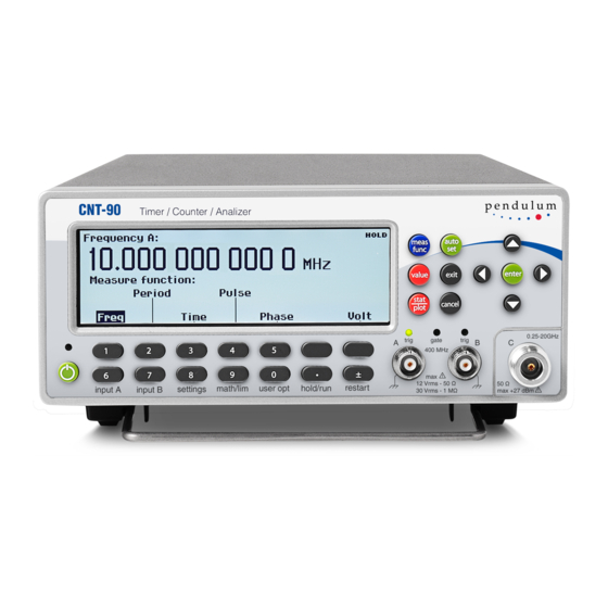
Pendulum CNT-90 Getting Started Manual
Hide thumbs
Also See for CNT-90:
- Programmer's handbook (264 pages) ,
- User manual (182 pages) ,
- Manual (51 pages)
Table of Contents
Advertisement
Quick Links
Timer/Counter/Analyzer
CNT-90, CNT-91, CNT-90/AN
Frequency Calibrator/Analyzer
CNT-91R
Microwave Counter/Analyzer
CNT-90XL
G E T T I N G S T A R T E D
M A N U A L
Part No.:
4031-600-90401
Revision:
1
Date:
6 March, 2020
Reproduction and distribution of this technical manual
is authorized for United States Government purposes.
© 2021 Pendulum Instruments.
All rights reserved.
Advertisement
Table of Contents

Subscribe to Our Youtube Channel
Summary of Contents for Pendulum CNT-90
- Page 1 Timer/Counter/Analyzer CNT-90, CNT-91, CNT-90/AN Frequency Calibrator/Analyzer CNT-91R Microwave Counter/Analyzer CNT-90XL G E T T I N G S T A R T E D M A N U A L Part No.: 4031-600-90401 Revision: Date: 6 March, 2020 Reproduction and distribution of this technical manual ©...
-
Page 2: Table Of Contents
Table of Contents Introduction Presentation Modes ..........3-4 VALUE ...................3-4 Introduction ..............1-2 STAT/PLOT ................3-4 About this Manual ............ 1-2 Remote ..............3-5 Warranty ................1-2 Hard Menu Keys ............3-5 Declaration of Conformity ........1-2 Input A ..............3-5 Safety Precautions ............ -
Page 3: Introduction
– Clearly mark the instrument to prevent its further operation. during the given warranty period. – Inform your Pendulum representative. For example, the instrument is likely to be unsafe if it is visibly damaged. -
Page 4: Preparation For Use
If the contents are incomplete or damaged, file a claim with the carrier immediately. Also notify Setting your local Pendulum sales or service organization in case repair The Counter can be connected to any AC supply with a or replacement may be required. -
Page 5: Rear Panel
Line Power Inlet Forced cooling is provided by means of a speed-controlled fan. AC 90-265 VRMS, 45-440 Hz, no rangeswitching needed. The CNT-90 rear panel layout. Reference Output Type Plate 10 MHz derived from the internal or the external reference,... -
Page 6: Operating The Counter
Chapter 3 Operating the Counter Introduction Getting Familiar with the Counter While this counter has a vast array of features and operating modes, the majority of the most useful functions can be learned The front panel is laid out in a logical fashion. Take a few seconds in just a few minutes. -
Page 7: Description Of Keys
Description of Keys Presentation Modes Power VALUE The ON/OFF key is a toggling secondary power switch. Part of the instrument is always on as soon as line power is applied, and this so-called standby condition is indicated by a red LED above the key. -
Page 8: Remote
• Histogram Mode Filter: On or Off. Pressing ENTER or the soft key below the text opens up the Filter Settings menu. See below. You can select a fixed 100 kHz analog Successive measurement results are converted into a histogram. The number of bins along the horizontal axis can be set by the user through the Settings ->... -
Page 9: Math/Limit
Trigger Hold-Off Math In this menu you can set the delay during which the stop trigger conditions are ignored after the measurement start. A typical use is to clean up signals generated by bouncing relay contacts. Statistics You can modify the measurement result mathematically by scaling or offsetting before presentation on the display. -
Page 10: Hold/Run
About (Information) Read status information about the instrument. • Model • Serial number • Firmware version • Factory-installed options • Calibration date • Setup Protect: ON or OFF. Only setup positions 1-10 can be Hold/Run protected against inadvertent overwriting. This key serves the purpose of manual arming. A pending Calibration Menu measurement will be finished and the result will remain on the display until a new measurement is triggered by pressing... -
Page 11: Exercises
Chapter 4 Exercises Preparation For these exercises you will need a ‘9X’ counter, a function generator and two BNC cables of approximately equal length. Set up the generator according to the following table, and connect the main output of the generator to input A of the counter. Built-In Math Processing With the built-in math functions, you can make post-processing operations like scaling and offsetting an easy benchtop task... -
Page 12: Under The Settings Menu
The measuring speed can be increased substantially if you set the trigger levels manually once, before a lengthy measurement sequence starts. Press INPUT A and choose MAN for the MAN/AUTO setting. Now press Trig to open the trigger level value input menu. Enter a level of +0.5 V. -
Page 13: Fall Time
Fall Time Phase Fall time is measured in a similar way by selecting Fall Time So far the counter has shown the timing relationship between instead of Rise Time above. the TTL and the main output of the generator as a time delay. You can also show this as phase shift between the signals. -
Page 14: Summary
Is this a feature? Well, yes and no. Yes, since this function gives touch-hold characteristics. No, since interrupted measurements giving false readouts may be misinterpreted by automatic test equipment and can even cause control SW to halt. The solution to this problem is the time-out function. –... - Page 15 CONTACT PENDULUM INSTRUMENTS SWEDEN phone +46 280 41122 info@pendulum-instruments.com UNITED STATES phone +1(866) 644-1230 us-office@pendulum-instruments.com © Pendulum Instruments 2021 March 06, 2020. CNT-90 Series rev.1 POLAND Specifications subject to change phone. +48 (58) 681 8901 info@pendulum-instruments.com or improvements without notice. www.pendulum-instruments.com...


Need help?
Do you have a question about the CNT-90 and is the answer not in the manual?
Questions and answers