Pendulum CNT-90 Series Manual
Hide thumbs
Also See for CNT-90 Series:
- Programmer's handbook (264 pages) ,
- User manual (182 pages) ,
- Getting started manual (30 pages)
Table of Contents
Advertisement
Quick Links
Advertisement
Table of Contents

Subscribe to Our Youtube Channel
Related Manuals for Pendulum CNT-90 Series


Summary of Contents for Pendulum CNT-90 Series
- Page 1 1 / 50...
- Page 2 1. GENERAL INFORMATION User Manual CNT-90/91/91R/91RAF/90XL About this Manual This manual contains directions for use that apply to the Timer/Counter/Analyzers CNT-90 and CNT-91 as well as the Frequency Calibrator/Analyzer CNT-91R and CNT-91R/AF and the Microwave Counter/Analyzer CNT-90XL. In order to simplify the references, these instruments are further referred to throughout this manual as the ‘9X’, whenever the information applies to all types.
-
Page 3: Design Innovations
30 ns pulse width. Optional built-in Li-Ion battery supply realizes instant high-precision measurements in the field and true UPS operation. Integrated high performance GPIB interface using SCPI commands. A fast USB interface that replaces the traditional but slower RS-232 serial interface Optional external GPIB-to Ethernet controller that allows connection to LAN . -
Page 4: Remote Control
starting at the trigger event. Charging is stopped at the leading edge of the first following clock pulse. The stored charge in the integrating capacitor represents the time difference between the start trigger event and the leading edge of the first following clock pulse. -
Page 5: Safety Precautions
Even though we know that you are eager to get going, we urge you to take a few minutes to read through this part of the introductory chapter carefully before plugging the line connector into the wall outlet. This instrument has been designed and tested for Measurement Category I, Pollution Degree 2, in accordance with EN/IEC 61010-1:2001 and CAN/CSA-C22.2 No. -
Page 6: If In Doubt About Safety
Clearly mark the instrument to prevent its further operation Fig. 1‑1 Do not overlook the safety instructions! Inform your Pendulum Instruments representative. For example, the instrument is likely to be unsafe if it is visibly damaged. 2.2.2.4. Disposal of Hazardous Materials CNT-90 &... -
Page 7: Installation
2.3.1. Check List The shipment should contain the following: Counter/Timer/Analyzer CNT-90/91 or Frequency Calibrator/Analyzer CNT-91R or CNT-91R/AF or Microwave Counter/Analyzer CNT-90XL Line cord Brochure with Important Information Certificate of Calibration Options you ordered should be installed. See Identification below. CD including the following documentation in PDF: Getting Started Manual User’s Manual Programmer’s Handbook... -
Page 8: Orientation And Cooling
It is possible to run the counter from an optional battery supply, Option 23/90. You must charge the battery before use or storage. The counter charges the battery automatically when connected to line power or an external DC source, whether the instrument is in standby or turned on. See the specifications for charging time in different modes of operation. -
Page 9: Rackmount Adapter
Fig. 1-2 Fold-down support for comfortable bench-top use. 2.3.3.6. Rackmount Adapter Fig. 1-3 Dimensions for rackmounting hardware. If you have ordered a 19-inch rack-mount kit for your instrument, it has to be assembled after delivery of the instrument. The rackmount kit consists of the following: 9 / 50... - Page 10 2 brackets, (short, left; long, right) 4 screws, M5 x 8 4 screws, M6 x 8 WARNING: Do not perform any internal service or adjustment of this instrument unless you are qualified to do so. Before you remove the cover, disconnect mains cord and wait for one minute.
- Page 11 Turn the devices upside down Remove the rubber feet in the plastic stand Loosen the screws underneath the rubber feet Remove the plastic stands Remove the four decorative plugs that cover the screw holes on the right and left side of the front panel. Use the following steps to complete the side by side rack mount installation for your products.
-
Page 12: Chapter 2: Using The Controls
3. Chapter 2: Using the Controls 3.1. Basic Controls A more elaborate description of the front and rear panels including the user interface with its menu system follows after this introductory survey, the purpose of which is to make you familiar with the layout of the instrument. See also the appendix. - Page 13 13 / 50...
-
Page 14: Secondary Controls
3.2. Secondary Controls 3.2.1. Connectors & Indicators 14 / 50... -
Page 15: Rear Panel
3.2.2. Rear Panel 15 / 50... - Page 16 Pulse Output [CNT-91(R) only]: User definable to serve as output for built-in pulse generator, gate indicator or alarm. Optional Main Input Connectors (not with Option 23/90): The front panel inputs can be moved to the rear panel by means of an optional cable kit. Note that the input capacitance will be higher. Type Plate: Indicates instrument type and serial number.
- Page 17 3.2.3. Rear Panel (CNT-91R/AF) Pulse Output [CNT-91(R) only]: User definable to serve as output for built-in pulse generator, gate indicator or alarm. Additional output frequencies Connectors: These connectors provide additional output frequencies which are, from left to right, 100kHz, 1MHz, 5MHz and 10MHz. Type Plate: Indicates instrument type and serial number.
-
Page 18: Select Function
3.3. Description of Keys 3.3.1. Power The ON/OFF key is a toggling secondary power switch. Part of the instrument is always ON as long as power is applied, and this standby condition is indicated by a red LED above the key. This indicator is consequently not lit while the instrument is in operation. - Page 19 Fig. 2-2 CNT-90XL: Select measurement function. Fig. 2-3 CNT-91(R): Select measurement function. The current selection is indicated by text inversion that is also indicating the cursor position. Select the measurement function you want by depressing the corresponding softkey right below the display. Alternatively, you can move the cursor to the wanted position with the RIGHT/LEFT arrow keys.
-
Page 20: Move Cursor
A higher value means faster settling time. By depressing this key twice within two seconds, you will enter the Preset mode, and a more extensive automatic setting will take place. In addition to the functions above, the following functions will be performed: Set Meas Time to 200 ms Switch off Hold-Off Set HOLD/RUN to RUN... - Page 21 Fig. 2-4 Main and aux. parameters. Value mode gives single line numerical presentation of individual results, where the main parameter is displayed in large characters with full resolution together with a number of auxiliary parameters in small characters with limited resolution. Fig.
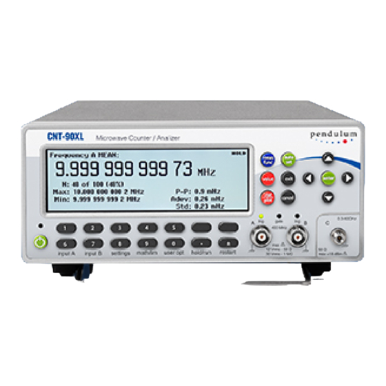
- Page 22 Fig. 2-6 Statistics presented numerically. In this mode the statistical information is displayed as numerical data containing the following elements: Mean: mean value Max: maximum value Min: minimum value P-P: peak-to-peak deviation Adev: Allan deviation Std: Standard deviation Histogram Fig. 2-7 Statistics presented as a histogram.
-
Page 23: Entering Numeric Values
Fig. 2-8 Running trend plot. This mode is used for observing periodic fluctuations or possible trends. Each plot terminates (if HOLD is activated) or restarts (if RUN is activated) after the set number of samples. The trend plot is always autoscaled based on the measured data, starting with 0 at restart. - Page 24 Fig. 2-9 Input settings menu. By depressing this key, the bottom part of the display will show the settings for Input A (B). The active settings are in bold characters and can be changed by depressing the corresponding softkey below the display.
- Page 25 Fig. 2-10 Selecting analog or digital filter. Input B The settings under Input B are equal to those under Input A. Settings This key accesses a host of menus that affect the measurement. The figure above is valid after changing the default measuring time to 10 ms.
- Page 26 per second and gives higher resolution. Burst Fig. 2-13 Entering burst parameters. This settings menu is active if the selected measurement function is BURST – a special case of FREQUENCY – and facilitates measurements on pulse-modulated signals. Both the carrier frequency and the modulating frequency – the pulse repetition frequency (PRF) –...
- Page 27 Trigger Hold-Off Fig. 2-16 The trigger hold-off submenu. A value input menu is opened where you can set the delay during which the stop trigger conditions are ignored after the measurement start. A typical use is to clean up signals generated by bouncing relay contacts. Statistics Fig.
- Page 28 Fig. 2-18 Selecting timebase reference source. Here you can decide if the counter is to use an Internal or an External timebase. A third alternative is Auto. Then the external timebase will be selected if a valid signal is present at the reference input. The EXT REF indicator at the upper right corner of the display shows that the instrument is using an external timebase reference.
- Page 29 Fig. 2-21 CNT-91(R): The ‘Misc’ submenu. The options in this menu are: Smart Measure with submenus: Smart Time Interval (valid only if the selected measurement function is Time Interval) The counter decides by means of timestamping which measurement channel precedes the other. Smart Frequency (valid only If the selected measurement function is Frequency or Period Average) By means of continuous timestamping and regression analysis, the resolution is increased for measuring times between 0.2 s and 100 s.
- Page 30 instrument will wait for a pending measurement to finish before outputting a zero result. The range is 10 ms to 1000 s. Interpolatator Calibration: By switching off the interpolator calibration, you can increase the measurement speed at the expense of accuracy. TIE (CNT-91 only): From a submenu you can either let the counter choose the reference frequency automatically (Auto) or enter it manually.
- Page 31 Fig. 2-25 Selecting Math formula for postprocessing. The display tells you that the Math function is not active, so press the Math Off key once to open the formula selection menu. Select one of the five different formulas, where K, L and M are constants that the user can set to any value. X stands for the current non-modified measurement result.
- Page 32 The Limit submenu is treated in a similar way, and its features are explored beginning on page 6-6. User Options Fig. 2-28 CNT-90: The User Options menu. Fig. 2-29 CNT-90XL & CNT-90 with Option 23/90: The User Options menu. Fig 2-30 CNT-91(R): The User Options menu.
- Page 33 Fig. 2-31 The menu appearance after pressing Save/Recall. Twenty complete front panel setups can be stored in non-volatile memory. Access to the first ten memory positions is prohibited when Setup Protect is ON. Switching OFF Setup Protect releases all ten memory positions simultaneously. The different setups can be individually labeled to make it easier for the operator to remember the application.
- Page 34 setting. Recall setup Fig. 2-34 Selecting memory position for recalling a measurement setup. Select the memory position from which you want to retrieve the contents in the same way as under Save current setup above. You can also choose Default to restore the preprogrammed factory settings. See the table on page 2-19 for a complete list of these settings.
- Page 35 Dataset Menu Fig. 2-36 The memory management menu after pressing Dataset. This feature is available in statistics mode only, and if HOLD has been pressed prior to initiating a measurement with RESTART. Up to 8 different datasets can be saved in FLASH memory, each containing up to 32000 samples. If the pending measurement has more than 32000 samples, only the last 32000 will be saved.
- Page 36 Fig. 2-38 Selecting active bus interface. Bus Type Select the active bus interface. The alternatives are GPIB and USB. If you select GPIB, you are also supposed to select the GPIB Mode and the GPIB Address. See the next two paragraphs. GPIB Mode There are two command systems to choose from.
- Page 37 Fig. 2-40 Selecting a specific test. Select one of them and press Start Test to run it. Digits Blank Jittery measurement results can be made easier for an operator to read by masking one or more of the LSDs on the display.
- Page 38 gate indicator alarm Press the softkey Output to open the submenu below. Fig. 2-42 Selecting output mode and pulse parameters. Off is the default mode and inhibits all activity on the output connector. The pulse generator parameters Period and Width can be entered by first pressing the corresponding softkeys, then setting the numerical values as usual.
-
Page 39: Default Settings
instrument firmware version timebase option & calibration date The CNT-91R reports “Rubidium” in this field. RF input option The CNT-90XL reports the upper frequency limit. Hold/Run This key serves the purpose of manual arming. A pending measurement will be finished and the result will remain on the display until a new measurement is triggered by pressing the RESTART key. -
Page 40: Chapter 3: Input Signal Conditioning
PARAMETER VALUE/SETTING Burst Sync Delay 400 ms Start Delay Meas. Time 200 ms Freq. Limit 400 MHz Miscellaneous Function FREQA Smart Frequency AUTO Smart Time Interval Meas. Time 200 ms Auto Trig Low Freq 100 Hz Timebase Reference AUTO Blank Digits Interpolator calibration Output (CNT-91(R)) 4. - Page 41 Fig. 3-1 Block diagram of the signal conditioning Fig. 3-2 Input settings menu. 4.1.1. Impedance The input impedance can be set to 1 MΩ or 50 Ω by toggling the corresponding softkey. CAUTION: Switching the impedance to 50 Ω when the input voltage is above 12 Vrms may cause permanent damage to the input circuitry.
- Page 42 When you measure symmetrical signals, such as sine and square/triangle waves, AC coupling filters out all DC components. This means that a 0 V trigger level is always centered around the middle of the signal where triggering is most stable. Fig.
- Page 43 Fig. 3-6 The menu choices after selecting FILTER. Analog Lowpass Filter The counter has analog LP filters of RC type, one in each of the channels A and B, with a cutoff frequency of approximately 100 kHz, and a signal rejection of 20 dB at 1 MHz. Accurate frequency measurements of noisy LF signals (up to 200 kHz) can be made when the noise components have significantly higher frequencies than the fundamental signal.
- Page 44 Use an oscilloscope for verification if you are in doubt about the frequency and waveform of your input signal. The cutoff frequency setting range is very wide: 1 Hz – 50 MHz Fig. 3-8 Digital LP filter operates in the measuring logic, not in the input amplifier. 4.1.5.
-
Page 45: How To Reduce Or Ignore Noise And Interference
Press SETTINGS->Misc->Auto Trig Low Freq. Use the UP/DOWN arrow keys or the numeric input keys to change the low frequency limit to be used during the trigger level calculation, (default 100 Hz). Confirm your choice and leave the SETTINGS menu by pressing EXIT/OK three times. 4.1.6. - Page 46 Fig. 3-10 Narrow hysteresis gives errone¬ous triggering on noisy signals. Fig. 3-11 Wide trigger hysteresis gives correct triggering. To ensure reliable measuring results, the counter has the following functions to reduce or eliminate the effect of noise: 10x input attenuator Continuously variable trigger level Continuously variable hysteresis for some functions Analog low-pass noise suppression filter...
-
Page 47: Trigger Hysteresis
To make reliable measurements possible on very noisy signals, you may use several of the above features simultaneously. Optimizing the input amplitude and the trigger level, using the attenuator and the trigger control, is independent of input frequency and useful over the entire frequency range. LP filters, on the other hand, function selectively over a limited frequency range. -
Page 48: How To Use Trigger Level Setting
Fig. 3-13 shows that less noise still affects the trigger point by advancing or delaying it, but it does not cause erroneous counts. This trigger uncertainty is of particular importance when measuring low frequency signals, since the signal slew rate (in V/s) is low for LF signals. To reduce the trigger uncertainty, it is desirable to cross the hysteresis band as fast as possible. - Page 49 Fig. 3-15 Timing error due to slew rate. When measuring LF sine wave signals with little noise, you may want to measure with a high sensitivity (narrow hysteresis band) to reduce the trigger uncertainty. Triggering at or close to the middle of the signal leads to the smallest trigger (timing) error since the signal slope is steepest at the sine wave center, see Fig.
-
Page 50: Chapter 4: Measuring Functions
However, stable readings are not necessarily correct; harmonic distortion can cause erroneous yet stable readings. Sine wave signals with much harmonic distortion, see Fig. 3-17, can be measured correctly by shifting the trigger point to a suitable level or by using continuously variable sensitivity, see Fig. 3-16. You can also use Trigger Hold-Off, in case the measurement result is not in line with your expectations.
Need help?
Do you have a question about the CNT-90 Series and is the answer not in the manual?
Questions and answers