Pendulum CNT-90 Getting Started Manual
Cnt-9x series timer/counter/analyzer frequency counter/analyzer microwave counter/analyzer
Hide thumbs
Also See for CNT-90:
- Programmer's handbook (264 pages) ,
- User manual (182 pages) ,
- Manual (51 pages)
Table of Contents
Advertisement
Quick Links
Download this manual
See also:
User Manual
Advertisement
Table of Contents

Subscribe to Our Youtube Channel
Related Manuals for Pendulum CNT-90


Summary of Contents for Pendulum CNT-90
- Page 2 4031 600 90401 May 2017- Seventh Edition © 2017 Pendulum Instruments / Altaria Services...
-
Page 3: Table Of Contents
Table of Contents 1 Introduction Orientation and Cooling ..2-4 Fold-Down Support ... 2-4 Introduction ....1-2 Rackmount Adapter . - Page 4 Remarks ....4-5 4 Exercises Volt Max/Min Measurements ..4-5 Preparation....4-2 Channel Swapping.
-
Page 5: Introduction
Chapter 1 Introduction... -
Page 6: About This Manual
Introduction About this Manual Introduction This manual contains directions for use that are common to all Timer/Counter/Analyzers Congratulations on your choice of instrument. in the CNT-9X series. It will serve you well for many years to come. In order to simplify the references, the CNT-9X is further referred to throughout this Even though we know that you are eager to manual as the '9X'. -
Page 7: Safety Precautions
Introduction of the instrument has taken place during Safety Precautions the given warranty period. This instrument has been designed and tested Caution and Warning for Measurement Category I, Pollution Degree Statements 2, in accordance with EN/IEC 61010-1:2001 and CAN/CSA-C22.2 No. 61010-1-04 (in- CAUTION: Shows where incorrect cluding approval). -
Page 8: If In Doubt About Safety
– Disconnect the line cord. – Clearly mark the instrument to prevent its further operation. – Inform your Pendulum representative. For example, the instrument is likely to be un- safe if it is visibly damaged. 1-4 Safety Precautions... -
Page 9: Preparation For Use
Chapter 2 Preparation for Use... -
Page 10: Unpacking
CD. It is in- a claim with the carrier immediately. Also no- cluded on the CD or can be downloaded free tify your local Pendulum sales or service orga- of charge from www.adobe.com. nization in case repair or replacement may be required. -
Page 11: Grounding
Preparation for Use trained personnel only, who are fully aware of Line Power Inlet the hazards involved. AC 90-265 V , 45-440 Hz, no range switching needed. The warranty commitments are rendered void if unauthorized access to the interior Reference Output of the instrument has taken place during the given warranty period. -
Page 12: Type Plate
Ref. Out Ext. Ref. In Ext. Arm In GPIB Conn. USB Conn. The CNT-90 rear panel layout. Fold-Down Support Type Plate For bench top use, a fold-down support is Here you can find the type number and the se- available for use underneath the counter. This... -
Page 13: Operating The Counter
Chapter 3 Operating the Counter... -
Page 14: Introduction
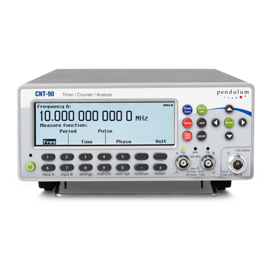
See also the figure on this page. It will help you locate the different keys faster. Soft Keys Presentation Modes Select Function Autoset/Preset Enter CNT-90 100ps / 300MHz TIMER / COUNTER / ANALYZE R pendulum TRIG GATE TRIG 0.2 8GHz... -
Page 15: Description Of Keys
Operating the Counter By depressing the AUTOSET key twice Description of Keys within two seconds, you will enter the Preset mode, which takes you another step further to- Power wards fully automatic settings for your current measurement. Such auxiliary functions as The ON/OFF key is a toggling secondary measuring time, mathematics, filter and arm- power switch. -
Page 16: Presentation Modes
Operating the Counter Presentation Modes • Numerical Mode • Histogram Mode VALUE • Trend Plot Mode Numerical Mode The Value Mode gives the result of the main measurement function as a numerical value in large characters with full resolution. In addi- tion, the results of supplementary measure- In this mode the statistical information is dis- ments are displayed in smaller characters with... -
Page 17: Remote
Operating the Counter factor. Enabled limits affect the autoscaling so desired position and then make the selection as to visualize the current measurements and by pressing the UP or the DOWN arrow keys. the set limits simultaneously. You can also use the ENTER key. Trend Plot Mode The selections that can be made in this menu are:... -
Page 18: Settings
Operating the Counter Settings Arming is the general term used for the means This key accesses a range of more sophisti- to control the actual start or stop of a measure- cated instrument settings that usually need not ment. When arming is used, the normal be changed for basic measurements. -
Page 19: Math/Limit
Operating the Counter the timeout system (if enabled) will hold • Pacing Time: Set the pacing time to a the last measurement result on screen value between 2 ms – 1000 s. only during the selected period of time (see next paragraph). Then the screen Timebase Reference will be blanked, and a pending bus query will read a zero result. -
Page 20: User Options
Operating the Counter multiplier or a mixer) is part of the system un- Save/Recall Menu der test. Twenty complete front panel setups can be stored in non-volatile memory; the first ten of Select one of four formulas and enter the con- them can be user-protected. -
Page 21: Hold/Run
Operating the Counter Interface Menu the RESTART key. The HOLD sign in the upper right corner of the screen indicates that Set the active interface to GPIB or USB and no new measurements are taking place. enter the GPIB address. •... - Page 22 Operating the Counter This page is intentionally left blank. 3-10 Description of Keys...
-
Page 23: Exercises
Chapter 4 Exercises... -
Page 24: Preparation
Modulation: Off will now read the frequency (1 MHz) on the display. Basic Startup Built-In Math Autoset Processing CNT-90 TIMER / COUNTER / ANALYZE R 100ps / 300MHz pendulum TRIG GATE TRIG Math/Limit 0.2 8GHz... -
Page 25: High-Speed Measurements
Exercises Under the INPUT Menus: To set up the counter to display any deviation from 1 MHz, press the MATH/LIM key and Auto trigger level settings in this model is so select Math. The display will show that Math fast that you will normally not notice any dif- is still Off. -
Page 26: Time Measurements
Exercises up to 2000 transferred measurements/s, each If you want to change the default values for individually triggered. If you save the results sample size, bin size or pacing time, then you to the internal memory of the instrument for can press the SETTINGS menu key and after later transfer, you can even attain an impres- that the STAT soft key. -
Page 27: Other Single-Channel Measurements
Exercises Rise Time Volt Max/Min Measurements Use the MEAS FUNC key to select Time, The counter can also measure the peak voltage values of your input signal. Use the MEAS Rise Time and A (for channel A). Press IN- PUT A and make sure the following settings FUNC key to select Volt. -
Page 28: Two-Channel Measurements
Exercises To avoid calculating the trigger levels yourself, Two-Channel you can let the counter measure the Auto levels Measurements and then store them as fixed values. Press INPUT A and check that Auto is still se- The counter can measure the timing relationship lected. -
Page 29: Auxiliary Functions
Exercises – – Press Recall Setup and select the mem- Press the SETTINGS key and then Misc ® Timeout Time. ory location in which you stored your original setup. – Calculate the time needed to decide if – Press EXIT/OK three times to return to the there is a signal present at the input. - Page 30 Altaria Services Sp. z.o.o. service@pendulum.se www.pendulum.se...
Need help?
Do you have a question about the CNT-90 and is the answer not in the manual?
Questions and answers