Advertisement
Quick Links
Advertisement

Related Manuals for Robe Anolis E-box Remote Basic Mini

Summary of Contents for Robe Anolis E-box Remote Basic Mini
- Page 1 QR code for user manual Version 1.1...
-
Page 2: Table Of Contents
E-box Remote Basic Mini Table of contents 1. Safety information ....................... 4 2. Fixture description ......................6 3. Mounting ..........................8 4. RDM manager ........................11 5. Software update of connected LED modules ..............15 6. Technical specifications ..................... 16 7. -
Page 3: Safety Information
1. Safety information FOR YOUR OWN SAFETY, PLEASE READ THIS USER MANUAL CAREFULLY BEFORE POWERING OR INSTALLING YOUR E-BOX REMOTE BASIC 240W! Save it for future reference. DANGEROUS VOLTAGE CONSTITUTING A RISK OF ELECTRIC SHOCK IS PRESENT WITHIN THIS UNIT! Make sure that the available voltage is not higher than stated on the fixture. - Page 4 off and on, the user is encouraged to try to correct the interference by one or more of the following measures: - Reorient or relocate the receiving antenna. - Increase the separation between the equipment and receiver. - Connect the equipment into an outlet on a circuit different from that to which the receiver is connected. - Consult the dealer or an experienced radio/TV technician for help.
-
Page 5: Fixture Description
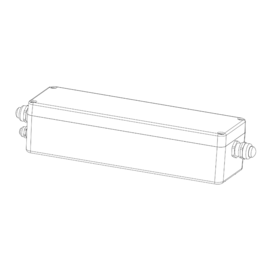
2. Fixture description View without top cover A - Top cover B - Top cover fastening screws C - Mounting holes 1 - LED Output (cable gland M20x1.5) 2 - Power IN (cable gland M20x1.5) 3 - DMX IN (cable gland M12x1.5) 4 -Connection board (RB4190) Connection points... - Page 6 Detail of PCB RB4190 Fuse 1 T 6.3A/500V AC Fuse 2 T 8A/250V AC Fuse 3 T 8A/250V AC...
-
Page 7: Mounting
3. Mounting Fixture must be installed by a qualified electrician in accordance with all national and local electrical and construction codes and regulations. Connecting the E-BOX REMOTE BASIC 240W can be done by a qualified person only! Note for cable glands. We recommend applying an adequate layer of the paste LOCTITE 5331 on the plastic holder of the cable gland before inserting it into the body of the gland. - Page 8 Eminere Remote connection CE version: Mark Function Wire LEDs + DATA + Orange DATA - White LEDS - Black Ground Not connected US version: Mark Function Wire LEDs + DATA + Orange DATA - White LEDS - Black Ground Green Example of connection Terminator...
- Page 9 Each line of Emineres Remote connected to the LED output of the E-box Remote Basic Mini has to be terminated at the last fixture. EITHER connect a 120 Ohm resistor between terminals D+ and D- as shown, OR terminate via RDM as described on page 14.
-
Page 10: Rdm Manager
4.RDM manager The RDM manager allows you to read information about connected LED modules and set their behaviour. The Emineres Remote can be controlled in the Pass Through mode only. RDM Manager and DMX controller cannot be connected at the same time. - Page 11 Examples of RDM manager screenshots. Initial screen of the RDM manager – Pass Through mode: Click on the LED device to show and set options in the Control panel: Occupied channels are displayed in the window DMX patch Click on the green arrow to save adjusted values to LED module...
- Page 12 If some DMX Preset shows xx instead of number of channels, it means that DMX preset is reserved for future using (e.g. DMX Presets 8-10). Options in the control panel:...
- Page 13 Last Eminere on each DMX line may be terminated by setting the ‘Manufacturer PID’ ’Terminator active’ to “1”, But ensure that the fixture is not already terminated with a 120 Ohm resistor as described on page 10. The option "Pixel swap" from RDM control panel allows you to swap a pixel order. Example: In case of reconnecting the E-box Remote Basic 240W on the other end of Emineres Remote line, the pixel order is not in succession:...
-
Page 14: Software Update Of Connected Led Modules
5.Software update of connected LED modules The software update of connected LED modules can be done by the Robe Universal Interface (or Robe Universal Interface WTX), DMX connection and the ROBE RDM Uploader software. The ROBE Uploader is a software for automatized software update of ROBE fixtures. -
Page 15: Technical Specifications
6.Technical specifications Input voltage 120-240 V AC; 277V AC Frequency 50/60Hz Power consumption 260W Inrush current (Typ.) 75A/230V (cold start) Fuse 1 T 6.3A/500V AC Fuse 2 T 8A/250V AC Fuse 3 T 8A/250V AC LED Output Number of outputs Voltage 48V DC Max output power... -
Page 16: Disposing Of The Product
Description of changes manual 30/06/2023 Device renamed June 30, 2023 Specifications are subject to change without notice. Copyright © 2023 Robe Lighting - All rights reserved Made in CZECH REPUBLIC by ROBE LIGHTING s.r.o. Palackeho 416/20 CZ 75701 Valasske Mezirici...
Need help?
Do you have a question about the Anolis E-box Remote Basic Mini and is the answer not in the manual?
Questions and answers