Table of Contents
Advertisement
Quick Links
MDT694
MDT694
MDT694
MDT694
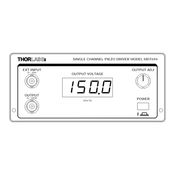
Single Channel Piezo Driver
Single Channel Piezo Driver
Single Channel Piezo Driver
Single Channel Piezo Driver
Operating Manual
EXT INPUT
OUTPUT
THORLABS, Inc.
435 Route 206N
Newton, NJ 07860 USA
SINGLE CHANNEL PIEZO DRIVER MODEL MDT694
(0 - 10V)
OUTPUT VOLTAGE
(0 - 150V)
Doc 3005-D02 Revision A 5/30/00
OUTPUT ADJ
(VOLTS)
POWER
Ph: (973) 579-7227
Fax: (973) 300-3600
www.thorlabs.com
Advertisement
Table of Contents

Related Manuals for THORLABS MDT694


Summary of Contents for THORLABS MDT694
- Page 1 MDT694 MDT694 Single Channel Piezo Driver Single Channel Piezo Driver Single Channel Piezo Driver Single Channel Piezo Driver Operating Manual SINGLE CHANNEL PIEZO DRIVER MODEL MDT694 EXT INPUT OUTPUT ADJ (0 - 10V) OUTPUT VOLTAGE OUTPUT (0 - 150V) POWER (VOLTS) THORLABS, Inc.
-
Page 2: Table Of Contents
Doc. No. 3005-D02 Revision A 5/30/00 Table of Contents TABLE OF CONTENTS SECTION 1.0 SPECIFICATIONS SECTION 2.0 OVERVIEW SECTION 3.0 DESCRIPTION Front Panel Features Controller Rear Panel Features SECTION 4.0 OPERATING INSTRUCTIONS Using the OUTPUT ADJ knob Using the EXT INPUT BNC Using the RS-232 Control (Optional) SECTION 5.0 APPLICATIONS NOTES Predicting Piezo Performance... -
Page 3: Section 1.0 Specifications
Doc. No. 3005-D02 Revision A 5/30/00 Section 1.0 Specifications Physical Features: Dimensions: 5 ½” x 2 ½” x 12” External Input Connector: Output Connector: Manual Control: 10-Turn Potentiometer RS-232 Interface: Female DB9 Number of Channels: Display Type: 3 ½ Digit LED Display Color: Orange Power Supply:... -
Page 4: Section 2.0 Overview
The MDT694 is a precision, low-noise, low-drift, high voltage controller for piezo actuators. The MDT694 provides both manual and external control of the piezo drive voltages. The MDT694 is an ideal driver for use with Thorlabs Piezo Actuators including the PE4 and the AE-series piezo elements. Typical applications include remote alignment of single-mode fiber couplers, remote positioning, Fabry-Perot etalons, etc. -
Page 5: Section 3.0 Description
OUTPUT ADJ Knob – This knob will adjust the output voltage from 0 to 150V DC. It can also be used as an offset for any external input, since it is summed with the EXT INPUT BNC. POWER Button – Press in to turn the MDT694 on. -
Page 6: Controller Rear Panel Features
1. Attach the piezo to the high voltage output connector on the MDT694 front panel. Note: the BNC center conductor is positive and the shield is at ground potential. Be certain to match piezo polarity to the connector since most piezo elements will be permanently damaged if connected backwards. -
Page 7: Using The Ext Input Bnc
Using the EXT INPUT BNC 1. Attach the piezo to the high voltage output BNC connector, located on the front panel of the MDT694. Note: the BNC center conductor is positive and the shield is at ground potential. Be certain to match piezo polarity to the connector since most piezo elements will be permanently damaged if connected backwards. -
Page 8: Hysteresis
A better approach would be to use an external encoder to give direct positional feedback. Section 6.0 Serial Interface (Optional) The MDT694 allows for an optional computer interface card to be installed. The rear panel DB9 connector will not be active unless the interface card is installed. -
Page 9: Fuse Replacement
Voltage Selector Switch will display the set operating voltage, either 115V or 230V) 4. Replace the fuse for the proper line voltage. The fuse rating is located on the rear panel of the MDT694 and in the Specifications section of this manual.
Need help?
Do you have a question about the MDT694 and is the answer not in the manual?
Questions and answers