
Subscribe to Our Youtube Channel
Related Manuals for THORLABS M30X


Summary of Contents for THORLABS M30X
- Page 1 M30X(/M) and M30XY(/M) Translation Stages M30X(/M) and M30XY(/M) DC Servo Motor Driven Translation Stages with Integrated Controller Kinesis User Guide Original Instructions HA0414T...
-
Page 2: Table Of Contents
M30X(/M) and M30XY(/M) Translation Stages Table of Contents Chapter 1 Introduction and Overview ......................1 1.1. Introduction ............................1 1.2. Kinesis PC Software Overview ...................... 2 1.2.1. Introduction ..........................2 1.2.2. Kinesis Server ........................... 2 1.2.3. Software Upgrades ........................3 Chapter 2 Safety ..............................4... -
Page 3: Chapter 1 Introduction And Overview
1.1. Introduction M30X(/M) and M30XY(/M) are compact 1- and 2- axes linear stages that use internally integrated brushed DC servo motors with optical linear encoders. Deployable in a multitude of applications, their innovative design eliminates the external motor housings that create mechanical clash points and impede access to the device being positioned. -
Page 4: Kinesis Pc Software Overview
1.2.1. Introduction The M30X(/M) and M30XY(/M) stages share many of the benefits of the Kinesis range of products. These include USB connectivity (allowing multiple units to be used together on a single PC), fully featured Graphical User Interface (GUI) panels, and extensive software function libraries for custom application development. -
Page 5: Software Upgrades
Kinesis Controls collection. This is available either by pressing the F1 key when running the Kinesis server, or via the Start menu, Start\Programs\Thorlabs\Kinesis\Kinesis Help. 1.2.3. Software Upgrades Thorlabs operate a policy of continuous product development and may issue software upgrades as necessary. Page 3 Rev B November 2021... -
Page 6: Chapter 2 Safety
M30X(/M) and M30XY(/M) Translation Stages Chapter 2: Safety Chapter 2 Safety 2.1. Safety Information For the continuing safety of the operators of this equipment, and the protection of the equipment itself, the operator should take note of the Warnings, Cautions and Notes throughout this handbook and, where visible, on the product itself. -
Page 7: Chapter 3 Installation
To minimize the possibility of this happening it is strongly recommended that any such modes that result in prolonged unresponsiveness be disabled before the Kinesis software is run. Please consult your system administrator or contact Thorlabs technical support for more details. Caution Some PCs may have been configured to restrict the user’s ability to load software, and on these systems the software... -
Page 8: Horizontal Mounting
M30X(/M) and M30XY(/M) Translation Stages Chapter 3: Installation 3.3. Horizontal Mounting Using a 2 mm (5/64") hex key as shown below, move the top platform to gain access to the mounting holes in the base plate, and secure using M6 or 1/4-20 bolts (not supplied). -
Page 9: Vertical Mounting
M30X(/M) and M30XY(/M) Translation Stages Chapter 3: Installation 3.4. Vertical Mounting The stages can be mounting in a vertical orientation using the M30A2(/M) adapter plate as shown below. It is recommended that the M30A1 cable clamp is also used as shown to support the cables. -
Page 10: Connector Detail
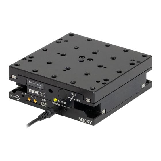
Connector Detail The side of the unit is fitted with a number of connectors that are common for both M30X and M30XY, as shown in Figure 4. Figure 4 Power and USB Connectors for the X (top) and XY (below) stage versions I/O 1 and I/O 2 - MMCX jack socket. -
Page 11: Chapter 4 Operation
4.3.1. Initial Setup 1) Run the software and check that the Graphical User Interface (GUI) panel appears and is active. For the M30X versions, only a single stage panel appears (Figure 5a) whereas for the M30XY version, 2 stage panels are shown, (Figure 5b): the number in the tab (circled) indicates the stage reference (1 = X;... -
Page 12: Homing Motors
M30X(/M) and M30XY(/M) Translation Stages Chapter 4: Operation 4.4. Homing Motors Homing the motor moves the actuator to the home limit switch and resets the internal position counter to zero. The process can be achieved after powering up and enabling the motor. -
Page 13: Jogging
M30X(/M) and M30XY(/M) Translation Stages Chapter 4: Operation 4.6. Jogging During PC operation, the motor actuators are jogged using the GUI panel arrow keys. There are two jogging modes available, ‘Single Step’ and ‘Continuous’. In ‘Single Step’ mode, the motor moves by the step size specified in the Step Distance parameter. -
Page 14: Stage/Axis Tab
Figure 9 Stage/Axis Tab These parameters were set automatically when the server automatically applied suitable defaults during boot up. These parameters should not be altered for pre-defined Thorlabs stages and actuators, as it may adversely affect the performance of the stage. -
Page 15: Chapter 5 Software Reference
Helpfile for more details. 5.2. GUI Panel The following screen shot shows the generic graphical user interface (GUI) displayed when accessing the M30X or M30XY Stages using the Kinesis software. Figure 10 M30XY Software GUI Position window - shows the position (in millimeters or degrees) of the motor. -
Page 16: Settings Panel
M30X(/M) and M30XY(/M) Translation Stages Chapter 5: Software Reference Error - lit when a fault condition occurs. Enable/Disable - applies and removes power to the motor. With the motor enabled, only the Disable button is visible, and with the motor disabled only the Enable button is visible. -
Page 17: Moves/Jogs Tab
M30X(/M) and M30XY(/M) Translation Stages Chapter 5: Software Reference 5.3.2. Moves/Jogs Tab Figure 11 Move/Jog Settings Position Display By default, the GUI panel will display position in real world units (mm). If required, the units can be changed to so that the display shows other positional units (cm, µm, inch). - Page 18 M30X(/M) and M30XY(/M) Translation Stages Chapter 5: Software Reference Jog - the motor moves by the distance specified in the Step Size parameter. Continuous - the motor continues to move until the jog signal is removed (i.e. jog button is released).
-
Page 19: Stage/Axis Tab
M30X(/M) and M30XY(/M) Translation Stages Chapter 5: Software Reference 5.3.3. Stage/Axis Tab Figure 13 Stage/Axis Settings Note This tab contains a number of parameters which are related to the physical characteristics of the particular stage being driven. They need to be set accordingly such that a particular stage is driven properly by the system. -
Page 20: I/O Tab
M30X(/M) and M30XY(/M) Translation Stages Chapter 5: Software Reference Ignore/Absent - The switch is missing, or should be ignored. 5.3.4. I/O Tab Figure 14 Triggering Settings IO Introduction The stages have two bidirectional IO ports (IO1 and IO2) that can be used to read an external logic signal or output a logic level to control external equipment. - Page 21 M30X(/M) and M30XY(/M) Translation Stages Chapter 5: Software Reference OUT - At Max Velocity - Trigger output active (level) when motor at 'max velocity'. OUT - At Position Steps Fwd - Trigger output active (pulsed) at pre-defined positions moving forward. Only one Trigger port at a time can be set to this mode.
- Page 22 M30X(/M) and M30XY(/M) Translation Stages Chapter 5: Software Reference Position PosIntervalFwd 15 mm Pos2 Fwd 12 mm Pos1 Rev StartPosRev 10 mm Pos1 Fwd St tP F d Time Trig Voltage Time Figure 15 Position Steps Triggering Example for a move from 0 to 20 mm and back.
-
Page 23: Advanced Tab
Figure 16 Advanced Settings Servo Loop (PID) Control Settings The M30X(/M) AND M30XY(/M) stages implement a full servo control loop for motor velocity and position control. The loop response to demanded position moves is determined via Proportional, Integration and Derivative settings. These settings can be altered using the ‘Servo Loop (PID) Control Settings’... -
Page 24: Chapter 6 Preventive Maintenance
The equipment contains no user serviceable parts. There is a risk of electrical shock if the equipment is operated with the covers removed. Only personnel authorized by Thorlabs Ltd and trained in the maintenance of this equipment should remove its covers or attempt any repairs or adjustments. Maintenance is limited to safety testing and cleaning as described in the following sections. -
Page 25: Chapter 7 Specifications
M30X(/M) and M30XY(/M) Translation Stages Chapter 7: Specifications Chapter 7 Specifications 7.1. M30X(/M) and M30XY(/M) Specifications Parameter M30X(/M) M30XY(/M) Stage Specifications Travel 30 mm (1.18") 30 mm x 30 mm (1.18" x 1.18") Max Speed 2.4 mm/s Acceleration 5.0 mm/s Bidirectional Repeatability ±1.0 µm... -
Page 26: Chapter 8 Regulatory
M30X(/M) and M30XY(/M) Translation Stages Chapter 8: Regulatory Chapter 8 Regulatory 8.1. Declarations Of Conformity 8.1.1. For Customers in Europe 8.1.2. For Customers in The USA This equipment has been tested and found to comply with the limits for a Class A digital device, pursuant to part 15 of the FCC rules. -
Page 27: Chapter 9 Thorlabs Worldwide Contacts
M30X(/M) and M30XY(/M) Translation Stages Chapter 9: Thorlabs Worldwide Contacts Chapter 9 Thorlabs Worldwide Contacts For technical support or sales inquiries, please visit us at www.thorlabs.com/contact for our most up-to-date contact information. Page 25 Rev B November 2021... - Page 28 www.thorlabs.com...
Need help?
Do you have a question about the M30X and is the answer not in the manual?
Questions and answers