Table of Contents
Advertisement
Quick Links
Advertisement
Table of Contents

Related Manuals for THORLABS KDC101


Summary of Contents for THORLABS KDC101
- Page 1 KDC101 DC Servo Motor Driver APT User Guide Original Instructions...
-
Page 2: Table Of Contents
Contents Chapter 1 Safety ..................... 4 1.1 Safety Information .................. 4 1.2 General Warnings .................. 4 Chapter 2 Introduction and Overview ............5 2.1 Introduction ..................... 5 2.2 K-Cube Controller Hub ................6 2.3 APT PC Software Overview ..............7 2.3.1 Introduction ...................... - Page 3 Appendix B Preventive Maintenance ............64 Appendix C Specifications and Associated Products ......65 Appendix D Motor Control Method Summary ........... 67 Appendix E DC Motor Operation - Background ........71 Appendix F Regulatory ................76 Appendix G Thorlabs Worldwide Contacts ..........79...
-
Page 4: Chapter 1 Safety
To minimize the possibility of this happening it is strongly recommended that any such modes that result in prolonged unresponsiveness be disabled before the APT software is run. Please consult your system administrator or contact Thorlabs technical support for more details. -
Page 5: Chapter 2 Introduction And Overview
DC brushed motors (up to 15V/2.5W operation) equipped with encoder feedback. The KDC101 has been optimised for 'out of the box' operation with the Thorlabs range of Z8 DC motor equipped opto-mechanical products, however highly flexible software settings and closed loop tuning also supports operation with a wide range of third party DC Servo motors and associated stages/actuators. -
Page 6: K-Cube Controller Hub
For power, a single way wall plug supply (KPS101) is available for powering a single K-Cube Driver. As a further level of convenience when using the new K-Cube Controllers Thorlabs also offers the 3-channel and 6-channel K-Cube Controller Hubs (KCH301 and KCH601). -
Page 7: Apt Pc Software Overview
K-Cube Brushed DC Servo Motor Driver 2.3 APT PC Software Overview 2.3.1 Introduction As a member of the APT range of controllers, the K-Cube DC Driver shares many of the associated software benefits. This includes USB connectivity (allowing multiple units to be used together on a single PC), fully featured Graphical User Interface (GUI) panels, and extensive software function libraries for custom application development. -
Page 8: Aptuser Utility
Chapter 2 2.3.2 APTUser Utility The APTUser application allows the user to interact with a number of APT hardware control units connected to the host PC. This program displays multiple graphical instrument panels to allow multiple APT units to be controlled simultaneously. All basic operating parameters can be altered and, similarly, all operations (such as motor moves) can be initiated. -
Page 9: Apt Config Utility
K-Cube Brushed DC Servo Motor Driver 2.3.3 APT Config Utility There are many system parameters and configuration settings associated with the operation of the APT Server. Most can be directly accessed using the various graphical panels, however there are several system wide settings that can be made 'off-line' before running the APT software. -
Page 10: Apt Server (Activex Controls)
Basic, Labview, Visual C++, C++ Builder, HPVEE, Matlab, VB.NET, C#.NET and, via VBA, Microsoft Office applications such as Excel and Word. Consider the ActiveX Control supplied for the KDC101 DC servo driver unit. This Control provides a complete user graphical instrument panel to allow the motor... -
Page 11: Software Upgrades
APT ActiveX Controls collection. This is available either by pressing the F1 key when running the APT server, or via the Start menu, Start\Programs\Thorlabs\APT\APT Help. 2.3.5 Software Upgrades Thorlabs operate a policy of continuous product development and may issue software upgrades as necessary. -
Page 12: Chapter 3 Getting Started
To minimize the possibility of this happening it is strongly recommended that any such modes that result in prolonged unresponsiveness be disabled before the APT software is run. Please consult your system administrator or contact Thorlabs technical support for more details. Caution Some PCs may have been configured to restrict the users ability to load software, and on these systems the software may not install/run. -
Page 13: Mechanical Installation
(KCH301 and KCH601). ) are also available - see Section 2.2. for further details. Full instructions on the fitting and use of the controller hub are contained in the handbook available at www.thorlabs.com Caution When siting the unit, it should be positioned so as not to impede the... -
Page 14: Using The Baseplate
Fig. 3.2 Rear Panel Connections The rear panel of the unit is fitted with a 15 pin D-type connector as shown above, which is compatible with Thorlabs DC servo motor actuators (refer to Appendix A for details of pin outs). -
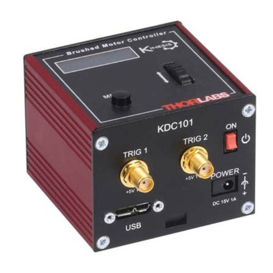
Page 15: Front Panel
POWER - A Standard 3.5 mm front panel jack connector for connecting the unit to a regulated DC power supply of 15 V, 1A. Thorlabs offers a compact, multi-way power supply unit (TPS008), allowing up to eight Driver K-Cubes to be powered from a single mains outlet. A single way wall plug supply (KPS101) for powering a single Driver K-Cube is also available. -
Page 16: Connect The Hardware
Chapter 3 3.4 Connect The Hardware 1) Perform the mechanical installation as detailed in Section 3.2. 2) Install the APT Software. Caution During items (3) to (6) the instructions should be followed strictly in the order stated. Problems may occur if the process is not performed in the correct sequence. - Page 17 3.5 Stage identification Most of the stages compatible with the KDC101 controller are fitted with an identification device. On power-up the KDC101 reads the stage identification and loads the correct operating parameters associated with the stage. When the controller is used with APT software, the type of stage is also reported to the GUI.
- Page 18 Chapter 3 3.6 Verifying Software Operation 3.6.1 Initial Setup 1) Ensure power is applied to the unit, then switch the unit ON using the switch on the front panel. 2) Wait until the power up sequence is complete, then run the APTUser utility and check that the Graphical User Interface (GUI) panel appears and is active.
-
Page 19: Chapter 4 Standalone Operation
4.1 Introduction The DC Driver K-Cube has been designed specifically to operate with the extensive range of Thorlabs DC motorised opto-mechanical products. The unit offers a fully featured motion control capability including velocity profile settings, limit switch handling, homing sequences and, for more advanced operation, adjustment of settings such as lead screw pitch and gearbox ratio, allowing support for many different actuator configurations. -
Page 20: Digital Display - Operating Mode
Chapter 4 4.2.2 Digital Display - Operating Mode During normal operation, the digital display shows the current position (in millimeters or degrees) and the current state of the motor (Stopped or Moving). If the stage being driven has been homed, the display will also show ‘Homed’. Brushed Motor Controller A t 0 . -
Page 21: Velocity Wheel Operation
K-Cube Brushed DC Servo Motor Driver This mode of operation is enabled by setting the ‘Wheel Mode’ to ‘Go To Position’ through the software GUI - see Section 6.3.4. or via the display menu, see Section 4.4.5. Note for Rotation Stage Users If the current absolute position is outside the 0 to 360 degree range, then "go to position"... -
Page 22: Settings Menu
Chapter 4 4.4 Settings Menu 4.4.1 Overview A t 0 . 0 0 0 0 m m S t o p p e d Press the MENU button MENU M e n u o p t i o n s Use the wheel to scroll through the menu options U s e w h e e l Press the MENU button to enter a particular option... -
Page 23: Menu Option - Go To Position
K-Cube Brushed DC Servo Motor Driver 4.4.2 Menu Option - Go to position A t 0 . 0 0 0 0 m m This mode is used to move to an absolute position. S t o p p e d MENU Press the MENU button, then use the wheel to scroll through the menu options. -
Page 24: Menu Option - Start Homing
Chapter 4 4.4.3 Menu Option - Start homing A t 2 . 0 0 0 0 m m This mode is used to home the stage. S t o p p e d MENU Press the MENU button, then use the wheel to scroll through the menu options. -
Page 25: Menu Option - Joystick Mode
K-Cube Brushed DC Servo Motor Driver 4.4.5 Menu Option - Joystick Mode This mode is used to set the operating mode of the A t 0 . 0 0 0 0 m m H o m e d S t o p p e d V joystick wheel. -
Page 26: Menu Option - Jog Step Size
Chapter 4 4.4.6 Menu Option - Jog Step Size A t 0 . 0 0 0 0 m m This mode is used to set the jog step size. H o m e d S t o p p e d V MENU M e n u o p t i o n s Press the MENU button, then use the wheel to scroll... -
Page 27: Menu Option - Teach Position
K-Cube Brushed DC Servo Motor Driver 4.4.7 Menu Option - Teach Position This mode is used to set the teach positions, used when the Joystick mode option is set to Jog to positions mode - see Section 4.4.5. To set Teach Position 1... A t 1 0 . -
Page 28: Menu Option - Brightness
Chapter 4 4.4.8 Menu Option - Brightness A t 0 . 0 0 0 0 m m In certain applications, it may be necessary to adjust the H o m e d S t o p p e d V brightness of the LED display. -
Page 29: Menu Option - Disable
4.4.11 Menu Option - Select Stage Most of the stages compatible with the KDC101 controller are fitted with an identification device. On power-up the KDC101 reads the stage identification and loads the correct operating parameters associated with the stage. However, some legacy stages are not fitted with an identification device. -
Page 30: Chapter 5 Pc Operation - Tutorial
Hardware configurations and parameter settings can be saved, which simplifies system set up whenever APT User is run up. Fig. 5.1 Typical APT User Screen 1) Wait until the KDC101 has started, then run the APT User program - Start/ Programs/Thorlabs/APT/APT User. - Page 31 K-Cube Brushed DC Servo Motor Driver 2) Notice how the actuator type is displayed in the ‘Settings’ window. See Section 5.11. and Section 6.3. for further details on the parameter values shown in the ‘Settings’ display. Fig. 5.2 DC Driver K-CubeSoftware GUI The APT User utility will be used throughout the rest of this tutorial to interface with the DC servo motor controller.
-
Page 32: Homing Motors
Chapter 5 5.3 Homing Motors Homing the motor moves the actuator to the home limit switch and resets the internal position counter to zero. The limit switch provides a fixed datum that can be found after the system has been powered up. Fig. -
Page 33: Moving To An Absolute Position
K-Cube Brushed DC Servo Motor Driver 5.4 Moving to an Absolute Position Absolute moves are measured in real world units (e.g. millimetres), relative to the Home position. 1) Click the position display. Fig. 5.4 Absolute Position Popup Window 2) Enter 8.0 into the pop up window 3) Click ‘OK’. -
Page 34: Changing Motor Parameters
Chapter 5 5.5 Changing Motor Parameters Moves are performed using a trapezoidal velocity profile (see Appendix E , Section E.1.3.). The velocity settings relate to the maximum velocities at which a move is performed, and the acceleration at which the motor speeds up from zero to maximum velocity. -
Page 35: Jogging
K-Cube Brushed DC Servo Motor Driver 5.6 Jogging During PC operation, the motor actuators are jogged using the GUI panel arrow keys. There are two jogging modes available, ‘Single Step’ and ‘Continuous’. In ‘Single Step’ mode, the motor moves by the step size specified in the Step Distance parameter. -
Page 36: Stopping The Stage
Chapter 5 5.7 Stopping the Stage The drive channel is enabled and disabled by clicking the ‘Enable’ button on the GUI panel. The green indicator in the button center is lit when the drive channel is enabled. Disabling the channel removes the drive power. During operation, the stage can be stopped at any time by clicking the ‘Stop’... -
Page 37: Graphical Control Of Motor Positions (Point And Move)
K-Cube Brushed DC Servo Motor Driver 5.8 Graphical Control Of Motor Positions (Point and Move) The GUI panel display can be changed to a graphical display, showing the position of the motor channel(s). Moves to absolute positions can then be initiated by positioning the mouse within the display and clicking. - Page 38 Chapter 5 Move Mode When ‘Move’ is selected, the motors move to an absolute position which corresponds to the position of the cursor within the screen. To specify a move: 1) Position the mouse within the window. For reference, the absolute motor position value associated with the mouse position is displayed in the 'Cursor Position field.
-
Page 39: Setting Move Sequences
K-Cube Brushed DC Servo Motor Driver 5.9 Setting Move Sequences This section explains how to set move sequences, allowing several positions to be visited without user intervention. For details on moving to absolute positions initiated by a mouse click – see Section 5.8. 1) From the Motor GUI Panel, select 'Move Sequencer' tab to display the Move Sequencer window. - Page 40 Chapter 5 3) Select 'New' to display the 'Move Editor' panel. Fig. 5.11 Move Editor Window Move data is entered/displayed as follows: Dist/Pos: - the distance to move from the current position (if 'Relative' is selected) or the position to move to (if 'Absolute' is selected). Dwell Time: - after the move is performed, the system can be set to wait for a specified time before performing the next move in the sequence.
- Page 41 K-Cube Brushed DC Servo Motor Driver 5) Enter the required move data into the Move Editor and click OK. The move data is displayed in the main window as shown below. Fig. 5.12 Main Window with Move Data 6) Repeat step 4 as necessary to build a sequence of moves. Move data can be copied, deleted, cut/pasted and edited by right clicking the data line(s) and selecting the appropriate option in the pop up menu (shown below).
-
Page 42: Creating A Simulated Configuration
To create a simulated configuration proceed as follows: 1) Run the APT Config utility - Start/Programs/Thorlabs/APT/APT Config. 2) Click the 'Simulator Configuration' tab. Fig. 5.15 APT Configuration Utility - Simulator Configuration Tab 3) Enter ‘LAB 1’... - Page 43 4) In the 'Simulator' field, check the ‘Enable Simulator Mode’ box. The name of the most recently used configuration file is displayed in the 'Current Configuration' window. 5) In the ‘Control Unit’ field, select ‘1 Ch DC Driver K-Cube (KDC101)’.
- Page 44 Chapter 5 6) In the ‘Enter 6 digit serial number’ field, enter a serial number for your KDC101 unit. Note Each physical APT hardware unit is factory programmed with a unique 8 digit serial number. In order to simulate a set of ‘real’ hardware the Config utility allows an 8 digit serial number to be associated with each simulated unit.
-
Page 45: Stage/Axis Tab
These parameters were set automatically when the actuator was connected. The APT server automatically applied suitable defaults for the parameters on this tab during boot up of APTUser. These parameters should not be altered for pre-defined Thorlabs stages and actuators selected using APT Config, as it may adversely affect the performance of the stage. -
Page 46: Chapter 6 Software Reference
Chapter 6 Software Reference 6.1 Introduction This chapter gives an explanation of the parameters and settings accessed from the APT software running on a PC. For information on the methods and properties which can be called via a programming interface, see Appendix D 6.2 GUI Panel The following screen shot shows the graphical user interface (GUI) displayed when accessing the DC Driver K-Cube using the APTUser utility. - Page 47 K-Cube Brushed DC Servo Motor Driver Travel - displays the range of travel (in millimeters or degrees) of the motor. Moving - lit when the motor is in motion. Enable - applies power to the motor. With the motor enabled, the LED in the button is lit.
-
Page 48: Settings Panel
Chapter 6 6.3 Settings Panel When the 'Settings' button on the GUI panel is clicked, the 'Settings' window is displayed. This panel allows motor operation parameters such as move/jog velocities, and stage/axis information to be modified. Note that all of these parameters have programmable equivalents accessible through the ActiveX methods and properties on this Control (refer to the Programming Guide in the APT helpfile for further details and to Section 2.3.4. - Page 49 K-Cube Brushed DC Servo Motor Driver Jogs Jogs are initiated by using the ‘Jog’ keys on the GUI panel (see Section 5.6.), or the Velocity Wheel on the top panel of the unit. Velocity Profile (specified in real world units, millimetres or degrees) MaxVel - the maximum velocity at which to perform a jog Accn/Dec - the rate at which the velocity climbs from minimum to maximum, and slows from maximum to minimum.
- Page 50 Chapter 6 Step Distance - The distance to move when a jog command is initiated. The step size is specified in real world units (mm or degrees dependent upon the stage). Backlash Correction - The system compensates for lead screw backlash during reverse direction moves, by moving passed the demanded position by a specified amount, and then reversing.
-
Page 51: Stage/Axis Tab
For Thorlabs stages, the system will recognise the stage and the APT server will automatically apply suitable defaults for the parameters on this tab during boot up of the software. These parameters should not be altered for pre-defined Thorlabs stages selected using APT Config, as it may adversely affect the performance of the stage. - Page 52 Chapter 6 Stage and Axis Type - For Thorlabs stages, the stage type is displayed automatically once the axis has been associated using the APTConfig utility. For third party stages, the display shows ‘Unknown’. Min Pos - the stage/actuator minimum position (typically zero).
- Page 53 K-Cube Brushed DC Servo Motor Driver Motor These parameters are used to set the 'resolution' characteristics of the DC servo motor connected to the selected channel. The resolution of the motor, combined with other characteristics (such as lead screw pitch) of the associated actuator, determines the overall resolution.
-
Page 54: Servo Loop Tab
Chapter 6 Persist Settings to Hardware - Many of the parameters that can be set for the DC Driver K-Cube can be stored (persisted) within the unit itself, such that when the unit is next powered up these settings are applied automatically. This is particularly important when the driver is being used manually in the absence of a PC and USB link. - Page 55 K-Cube Brushed DC Servo Motor Driver Servo Loop (PID) Control Settings The DC Driver K-Cube implements a full servo control loop for motor velocity and position control. The loop response to demanded position moves is determined via Proportional, Integration and Derivative settings. These settings can be altered using the ‘Servo Loop (PID) Control Settings’...
-
Page 56: Panel/Triggering Tab
Chapter 6 6.3.4 Panel/Triggering Tab Fig. 6.6 DC Driver K-Cube - Panel/Triggering Settings Adjustment Wheel Settings The velocity wheel is sprung such that when released it returns to it’s central position. In this central position the motor is stationary. As the wheel is moved away from the center, the motor begins to move;... - Page 57 K-Cube Brushed DC Servo Motor Driver Wheel Direction The direction of a move initiated by the velocity wheel is specified as follows: Disabled - The wheel is disabled to remove any unwanted motion due to accidental movement of the wheel. Direction Sense Positive - Upwards rotation of the wheel results in a positive motion (i.e.
- Page 58 Chapter 6 Triggering Introduction The K-Cube motor controllers have two bidirectional trigger ports (TRIG1 and TRIG2) that can be used to read an external logic signal or output a logic level to control external equipment. Either of them can be independently configured as an input or an output and the active logic state can be selected High or Low to suit the requirements of the application.
- Page 59 K-Cube Brushed DC Servo Motor Driver Output Trigger Modes When the Trig 1 Mode and Trig 2 Mode parameters are configured as outputs, the TRIG ports can be used as a general purpose digital output, or to indicate motion status or to produce a trigger pulse at configurable positions as follows: Digital Output - General purpose logic output (set using the LLSetGetDigOPs method).
- Page 60 Chapter 6 Cycles) allows the uni- or bidirectional position triggering sequence to be repeated a number of times. PosIntervalFwd 15 mm Pos2 Fwd 12 mm Pos1 Rev StartPosRev 10 mm StartPosFwd Pos1 Fwd Time Trig Voltage Time Fig. 6.7 Position Steps Triggering Example for a move from 0 to 20 mm and back.
-
Page 61: Defaults Tab
K-Cube Brushed DC Servo Motor Driver 6.3.5 Defaults Tab If adjustment of the parameter values previously described has resulted in unstable or unsatisfactory system response, this tab can be used to reset all parameter values to the factory default settings. To restore the default values: 1) Click the ‘Reset Parameter Defaults in the Controller’... -
Page 62: Rotation Stagestab
Chapter 6 6.3.6 Rotation StagesTab Absolute Position Reporting Mode This setting relates to the way in which the angular position is displayed on the GUI panel. There are two options: Equivalent Angle 0 to 360 degrees – The maximum displayed position is 359.99°. If a stage is driven past the 360°... -
Page 63: Appendix A Rear Panel Connector Pinout Detail
DO NOT connect a motor actuator while the K-Cube is powered up. Only use motor drive cables supplied by Thorlabs, other cables may have incompatible wiring. Please contact tech support for details on use with Thorlabs legacy Z6 series DC Servo Motors. -
Page 64: Appendix B Preventive Maintenance
The equipment contains no user servicable parts. There is a risk of electrical shock if the equipment is operated with the covers removed. Only personnel authorized by Thorlabs Ltd and trained in the maintenance of this equipment should remove its covers or attempt any repairs or adjustments. Maintenance is limited to safety testing and cleaning as described in the following sections. -
Page 65: Appendix C Specifications And Associated Products
Appendix C Specifications and Associated Products C.1 Specifications Parameter Value Motor Output Motor Drive Voltage ±12 to ±15V (Depending on Supply) Motor Drive Current 150mA (Cont) >250 mA (peak) Motor Drive Type 8-bit Sign/Magnitude PWM Control Algorithm Digital PID Filter (16bit) Position Feedback: 5V Single Ended Quadrature Encoder (QEP) Input... - Page 66 Appendix C Recommended Motor Requirements Peak Power 2.5W Rated Current 10mA to 200mA (Nominal) Motor Type Brushed DC Coil Resistance 5 to 50Ω Position Control Closed loop Encoder C.2 Associated Products Product Name Part Number 6mm DC Servo Motor Actuator, 1/4”-80 Z806 6mm DC Servo Motor Actuator, 1/4”-80, Vaccuum Rated Z806V...
-
Page 67: Appendix D Motor Control Method Summary
Appendix D Motor Control Method Summary The 'Motor' ActiveX Control provides the functionality required for a client application to control one or more of the APT series of motor controller units. To specify the particular controller being addressed, every unit is factory programmed with a unique 8-digit serial number. - Page 68 Appendix D GetHWCommsOK Gets the hardware communications OK flag. GetHWLimSwitches Gets the limit switch configuration settings. GetIndicatorLEDMode Gets the front panel indication LED operating mode. GetJogMode Gets the jogging button operating modes. GetJogMode_Mode Get the jogging button operating mode (returned by value).
- Page 69 K-Cube Brushed DC Servo Motor Driver GetStageAxis Gets the stage type information associated with the motor under control. GetStageAxisInfo Gets the stage axis parameters. GetStageAxisInfo_MaxPos Gets the stage maximum position (returned by value). GetStageAxisInfo_MinPos Gets the stage minimum position (returned by value).
- Page 70 Appendix D SetDispMode Sets the GUI display mode. SetHomeParams Sets the homing sequence parameters. SetHWLimSwitches Sets the limit switch configuration settings. SetIndicatorLEDMode Sets the front panel indication LED operating modes (Cube drivers). SetJogMode Sets the jogging button operating modes. SetJogStepSize Sets the jogging step size.
-
Page 71: Appendix Edc Motor Operation - Background
Appendix E DC Motor Operation - Background E.1 How A DC Motor Works E.1.1 General Principle A DC motor works by converting electric power into mechanical energy (movement). This is achieved by forcing current through a coil and producing a magnetic field, which in turn, spins the motor. - Page 72 Appendix E Both forces are of equal magnitude. At 180°, the same phenomenon occurs, but segment A-B is forced down and C-D is forced up. In the 90° and 270° positions, the brushes are not in contact with the voltage source and no force is produced. In these two positions, the rotational kinetic energy of the motor keeps it spinning until the brushes regain contact.
- Page 73 K-Cube Brushed DC Servo Motor Driver E.2 Positioning a Stage E.2.1 General Whenever a command is received to move a stage, the movement is specified in motion units, (e.g. millimetres). This motion unit value is converted to encoder counts before it is sent to the stage by the APT software. Each motor in the system has an associated electronic counter in the controller, which keeps a record of the net number of encoder counts moved.
- Page 74 Appendix E Datum switch +ve limit switch -ve limit switch (or stop) Linear stage Rotary stage Fig. E.3 Stage limit switches E.2.4 Minimum and Maximum Positions These positions are dependent upon the stage or actuator to which the motors are fitted, and are defined as the minimum and maximum useful positions of the stage relative to the ‘Home’...
- Page 75 K-Cube Brushed DC Servo Motor Driver E.3 Error Correction E.3.1 Backlash correction The term backlash refers to the tendency of the stage to reach a different position depending on the direction of approach. Backlash can be overcome by always making the last portion of a move in the same direction, conventionally the positive direction.
-
Page 76: Appendix F Regulatory
Appendix F Regulatory F.1 Declarations Of Conformity F.1.1 For Customers in Europe See Section F.3. F.1.2 For Customers In The USA This equipment has been tested and found to comply with the limits for a Class A digital device, persuant to part 15 of the FCC rules. These limits are designed to provide reasonable protection against harmful interference when the equipment is operated in a commercial environment. - Page 77 • left over parts of units disassembled by the user (PCB's, housings etc.). If you wish to return a unit for waste recovery, please contact Thorlabs or your nearest dealer for further information. F.2.2 Waste treatment on your own responsibility If you do not return an "end of life"...
- Page 78 Appendix F F.3 Certificate of Conformity HA0363T Rev D Jan 2017...
-
Page 79: Appendix G Thorlabs Worldwide Contacts
Fax: +86 (0)21-32513480 email: sales.uk@thorlabs.com www.thorlabs.com Support: email: chinasales@thorlabs.com techsupport.uk@thorlabs.com Brazil France Thorlabs Vendas de Fotônicos Ltda. Thorlabs SAS Rua Riachuelo, 171 109, rue des Côtes 78600 Maisons-Laffitte São Carlos, SP 13560-110 France Brazil Tel: +33 (0) 970 444 844... - Page 80 Thorlabs Inc. Thorlabs Ltd. 56 Sparta Ave 1 Saint Thomas Place, Ely Newton, NJ07860 Cambridgeshire CB7 4EX, Tel: +1 973 579 7227 Tel: +44 (0) 1353 654440 Fax: +1 973 300 3600 Fax: +44 (0) 1353 654444 www.thorlabs.com www.thorlabs.com...
Need help?
Do you have a question about the KDC101 and is the answer not in the manual?
Questions and answers