Intermatic EJ351 Installation And User Instructions
Indoor wall switch timer
Hide thumbs
Also See for EJ351:
- User manual ,
- Owner's instruction manual (2 pages) ,
- Installation and user instructions (2 pages)
Advertisement
MODEL EJ351
Installation and User Instructions
Specifications
•
500W maximum, 40W minimum (incandescent)
NOTE: Derate to 400W maximum when 2 or more timers are
installed in the same wall box.
•
120 VAC, 60 Hz
•
30 minute minimum ON/OFF period
•
24-hour repeat cycle
•
Up to 48 daily operation events (24 ON, 24 OFF)
•
Random Variability: For "lived in" look, ON/OFF times vary at
least 7 minutes from the set time and at least 15 minutes from
the previous day.
•
Power Failure Memory Protection: Depending on conditions at
time of power failure, will retain settings up to 15 minutes.
•
Operate at Room Temperature: 32°F (0°C) to 104°F (40°C)
•
Electrical shock hazard. Risk of injury or death. Remove electrical power at
service panel before installing.
•
Risk of fire. Do not use timer to control devices that could have dangerous
consequences due to inaccurate timing such as sun lamps, sauna, heaters,
crock pots, etc.
•
Follow local electrical codes during installation.
•
Do not use with PAR or "R"-type outdoor flood lamps larger than 150 watts.
•
Use ONLY with incandescent lights. Do not use with compact fluorescent
lamps (CFLs), starter or other electronic ballasts, mercury vapor lights, ap-
pliances, radios TVs, stereos, etc.
•
Do not use in combination with separate dimmers or photoelectric switches.
•
In rare cases, may cause radio or TV interference which can be resolved by
adjusting the antenna, moving the receiver, or plugging the receiver into a
different AC outlet.
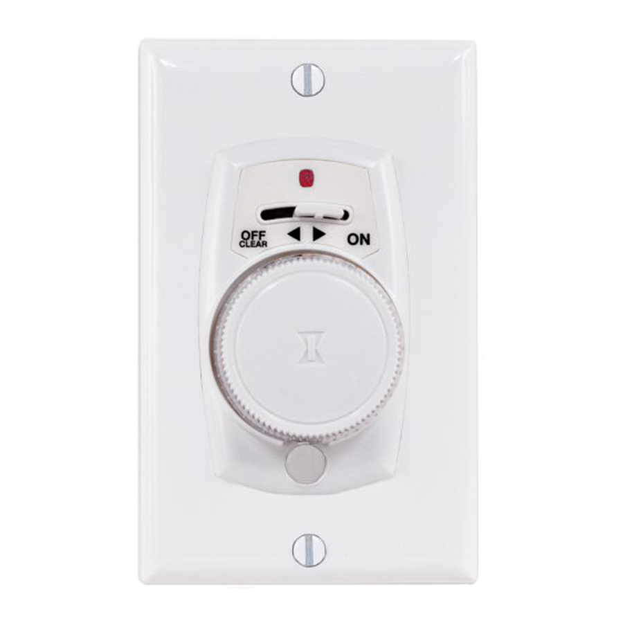
Installing the Switch Timer
Red
Indicator
Light
Control
Lever
Control
Panel
Plastic
Push-Button
Screw
Time Dial
Cover
The EJ351 Switch Timer replaces a standard toggle switch.
Installation requires the following tools:
•
Flat-blade screwdriver
•
Phillips-head screwdriver
1.
Turn off power at the service panel by REMOVING FUSE or
TURNING THE CIRCUIT BREAKER OFF.
2.
Remove the switchplate and existing wall switch.
3.
Remove the dial and control panel from the switch timer.
Gently and firmly pull straight out to remove.
4.
Trim building wires to 7/16" as shown.
WARNING
NOTICE
INCLUDED FOR INSTALLATION:
Flat
Head
Twist
Screws
Connectors
(2)
(2)
Dome
Head
Screw
(1)
7/16"
Indoor Wall Switch Timer
5.
Connect two wires from the wall
to the BLACK wires from the
switch timer, using the twist
connectors provided.
6.
If the old switch had a ground
wire (normally connected to a
green hex-head screw), fasten it
securely to the metal box or timer metal bracket.
7.
Make sure all twist connectors are tight.
8.
Tuck wires into wall box leaving room for the device.
9.
Using 2 flat-head screws provided, mount the switch timer
into the wall box.
10.
Position the wall plate over the switch timer,
making sure the upper screw hole of the wall
plate is over the RED indicator light.
11.
Install the control panel over the wall plate as
follows:
a.
Position the clear plastic lens into the up-
per screw hole in the wall plate.
b.
Make sure the post next to the knob shaft
is properly aligned with the control lever
hole in the control panel.
c.
Install the dome-head screw in the bottom
hole of the control panel, on through the
bottom hole of the switch plate. Tighten
snugly but DO NOT OVERTIGHTEN.
d.
Install the white plug over the dome-head
screw.
12.
Press the dial onto the switch timer's shaft.
Align the flat side of the shaft with the flat side
within the dial.
13.
Turn power back on at the service panel.
Programming Using the RAPID Method
Use this procedure to manually program ON/OFF settings.
1. Move the control lever to the OFF-CLEAR position for about
20 seconds. The red indicator light will go off and any
previous time settings will be cleared from memory.
2. Move the control lever to the ON position. The Red indicator
light will start flashing.
NOTE: Should the Red indicator light remain ON,
move the control lever to the OFF - CLEAR position
for 20 minutes.
3. Rotate the time dial clockwise at least one click, stopping at
Plastic
the present time.
Screw
NOTE: During programming, be careful not to press the
Cover
dial while turning it. If you press the dial, you will
(1)
accidentally set a wrong time.
4. Press the dial once to set the present time. The Red indicator
light will go off.
5. Rotate the time dial clockwise to the first desired ON time.
The Red light will pulse momentarily with each click.
6. Press the dial once to enter the ON time. The light controlled
by the switch timer will turn ON.
7. Rotate the time dial clockwise to the desired OFF time.
8. Press the dial once to enter the OFF time. The light controlled
by the switch timer will turn OFF.
9. Repeat Steps 5-8 for each additional ON/OFF setting.
10. Continue to rotate the time dial until the Red indicator
light comes on and stays ON, indicating that the switch timer
is in AUTOMATIC mode.
BLACK
BLACK
RED
Indicator
Light
RED Indicator Light
Clear
Plastic
Lens
Align with
Hole in
Control Panel
Advertisement
Table of Contents

Related Manuals for Intermatic EJ351


Summary of Contents for Intermatic EJ351
- Page 1 4. Press the dial once to set the present time. The Red indicator light will go off. The EJ351 Switch Timer replaces a standard toggle switch. 5. Rotate the time dial clockwise to the first desired ON time. Installation requires the following tools: The Red light will pulse momentarily with each click.
-
Page 2: Troubleshooting Guide
LIMITED ONE-YEAR WARRANTY If within one (1) year from the date of purchase, this product fails due to a defect in material or workmanship, Intermatic Incorporated will repair or replace it, at its sole option, free of charge. This warranty is extended to the original household purchaser only and is not transferable.
Need help?
Do you have a question about the EJ351 and is the answer not in the manual?
Questions and answers