Advertisement
Quick Links
Download this manual
See also:
User Manual
INSTRUCTION
MANUAL
G-550
VERTEX STANDARD CO., LTD.
4-8-8 Nakameguro, Meguro-Ku, Tokyo 153-8644, Japan
VERTEX STANDARD
US Headquarters
17210 Edwards Rd., Cerritos, CA 90703, U.S.A.
International Division
8350 N.W. 52nd Terrace, Suite 201, Miami, FL 33166, U.S.A.
YAESU EUROPE B.V.
P.O. Box 75525, 1118 ZN Schiphol, The Netherlands
YAESU UK LTD.
Unit 12, Sun Valley Business Park, Winnall Close
Winchester, Hampshire, SO23 0LB, U.K.
YAESU GERMANY GmbH
Am Kronberger Hang 2, D-65824 Schwalbach, Germany
VERTEX STANDARD HK LTD.
Unit 5, 20/F., Seaview Centre, 139-141 Hoi Bun Road,
Kwun Tong, Kowloon, Hong Kong
Advertisement

Related Manuals for Yaesu G-550


Summary of Contents for Yaesu G-550
- Page 1 17210 Edwards Rd., Cerritos, CA 90703, U.S.A. International Division 8350 N.W. 52nd Terrace, Suite 201, Miami, FL 33166, U.S.A. YAESU EUROPE B.V. P.O. Box 75525, 1118 ZN Schiphol, The Netherlands YAESU UK LTD. Unit 12, Sun Valley Business Park, Winnall Close Winchester, Hampshire, SO23 0LB, U.K.
-
Page 3: Specifications
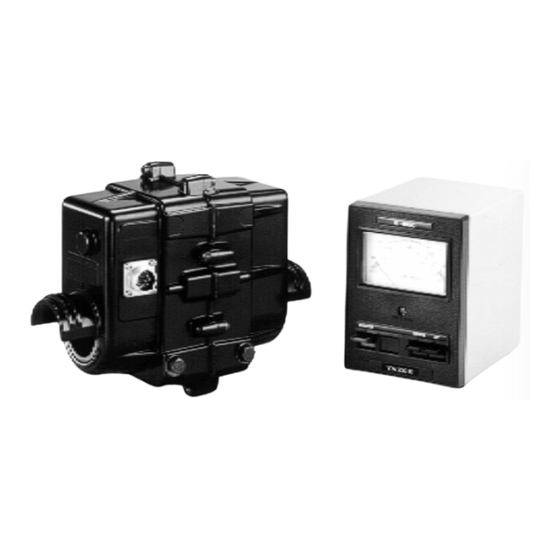
MEDIUM-DUTY ANTENNA ELEVATION ROTATOR & CONTROLLER The Yaesu G-550 provides 180° elevation control of unidirectional satellite antenna arrays under remote control from the station operating position. The factory-lubri- cated rotator unit is housed in weatherproof melamine resin coated die-cast alumi- num, to provide maintenance-free operation under all climatic conditions. -
Page 4: Unpacking And Inspection
Note that cable is not included with the rotator, as the length must be determined case- by-case. Contact your Yaesu dealer to obtain the length of cable your installation requires. For runs of over 100 feet, use #18 AWG instead of #20 AWG. - Page 5 H If both clockwise (up). H Remember to turn the controller off when the rotator is not in use. G-550 I switch. The meter lamp should light and the meter indicate switch and confirm that the rotator slowly stops. switch instead of the switches are pressed at the same time, the rotator turns Terminal 7 is not used.
- Page 6 G-550 I ELEVATION INDICATOR CALIBRATION Turn the controller off and note the position of the meter needle, which should be precisely at the left edge of the scale. If not, adjust the zero adjust screw beneath the meter face. 0. ADJ Screw Press the switch to align the 180°...
- Page 7 ROTATOR INSTALLATION The G-550 is designed to accommodate small- and medium-size antenna arrays. The maximum safe load depends on the physical size of the antenna, method and quality of mechanical installation, and maximum wind velocity at the installation site. The diagrams below show several recommended installations. Notice that the pre- ferred mounting method requires that each antenna be attached to the boom at its center of gravity, with the boom there attached to the rotator at its center of gravity.
- Page 8 G-550 I Be sure to leave enough slack in both the elevation control cable and the coaxial cable feedline around the azimuth rotator so the antenna can rotate 180° without straining the cable or feedline. For dual parallel arrays, feedlines should be taped to the boom on either side of the rotator, with enough slack left to allow 180°...
- Page 9 G-550 I...
- Page 10 G-550 I Note...
- Page 12 Copyright 2001 VERTEX STANDARD CO., LTD. All rights reserved No portion of this manual may be reproduced without the permission of VERTEX STANDARD CO., LTD. Printed in Japan.
Need help?
Do you have a question about the G-550 and is the answer not in the manual?
Questions and answers