Advertisement
Quick Links
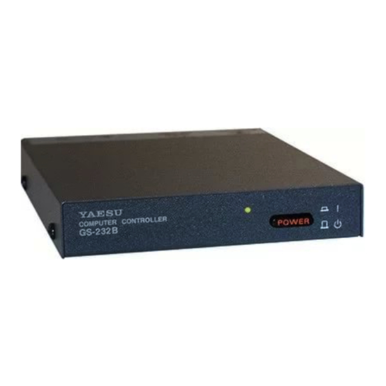
GS-232B
Computer Control Interface for
Antenna Rotators
YAESU MUSEN CO., LTD.
Tennozu Parkside Building
2-5-8 Higashi-Shinagawa, Shinagawa-ku, Tokyo 140-0002 Japan
YAESU USA
6125 Phyllis Drive, Cypress, CA 90630, U.S.A.
YAESU UK
Unit 12, Sun Valley Business Park, Winnall Close
Winchester, Hampshire, SO23 0LB, U.K.
Advertisement

Subscribe to Our Youtube Channel
Related Manuals for Yaesu GS-232B


Summary of Contents for Yaesu GS-232B
- Page 1 GS-232B Computer Control Interface for Antenna Rotators YAESU MUSEN CO., LTD. Tennozu Parkside Building 2-5-8 Higashi-Shinagawa, Shinagawa-ku, Tokyo 140-0002 Japan YAESU USA 6125 Phyllis Drive, Cypress, CA 90630, U.S.A. YAESU UK Unit 12, Sun Valley Business Park, Winnall Close Winchester, Hampshire, SO23 0LB, U.K.
- Page 3 The async serial line can be configured for serial data GX-500 Automatic Control Adapter, follow the proce- rates from 1200 to 9600 baud. The GS-232B has a DB-9 dures in the GX-500 manual before installing the GS- “male” connector for connection to the (RS-232C) COM 232B.
-
Page 4: Connector Pinouts
eneral onnector inouts Power Requirements: Serial I/O: DC 12 V, 70 mA Case Size: 4.3” (W) x 0.8” (H) x 5.4” (D) 9-pin DB-9 connector (RS-232C connector) (110 x 21 x 138 mm) Pin 2 - Tx Data Weight (approx.): 13.4 oz. - Page 5 upplieD ccessories vailable ptions Connection Cable Control cable for the Azimuth Rotator 1 ....1 pc C-1000 (“5-pin” “Min-DIN” cable) (for SDX series Azimuth Rotator) Control cable for the A Rotator 2 ....1 pc PA-44B, PA-44C, PA-44U, PA-44H 3 AC Adapter (“Dual 5-pin”...
-
Page 6: P Ower & C Ontrol C Onnections
Negative ceived from the GS-232B. (–) DC terminal. The GS-232B requires 70 mA. The supplied cable has a 500-mA fast-blow fuse. Use only the same type fuse for replacement. - Page 7 Negative terminal, and the black lead connects to the Negative (–) DC terminal. The GS-232B requires 70 mA. The (–) DC terminal. The GS-232B requires 70 mA. The supplied cable has a 500-mA fast-blow fuse. Use only supplied cable has a 500-mA fast-blow fuse.
-
Page 8: P Ower & C Ontrol
Negative Connect the 8-pin connector of the C-1000 Connec- (–) DC terminal. The GS-232B requires 70 mA. The tion cable to the exposed 8-pin connector located the supplied cable has a 500-mA fast-blow fuse. Use only rear left corner in the controller. - Page 9 ) on the computer keyboard to dis- ntEr cable to the RS-232C connector on the rear panel of able the 450° rotation capability of the GS-232B. To restore 450° rotation capability, press [ P45 ] [ ] (P, the GS-232B.
- Page 10 DXa/DXc/sDX series zimuth otator Azimuth Offset Null Azimuth A-D Calibration From the Controller panel, set the Rotator fully coun- From the Controller panel, set the Rotator fully clock- ter-clockwise (set to 0°). wise (to the right). Press [ O ] [ ] (the letter “oh,” and “E ...
- Page 11 G-400 a zimuth otator Azimuth Offset Null Azimuth A-D Calibration From the Controller panel, set the Rotator fully coun- From the Controller panel, set the Rotator fully clock- ter-clockwise (set to 0°). wise (to the right). Press [ O ] [ ] (the letter “oh,” and “E ...
- Page 12 G-5400b/-5600b a otator Azimuth Offset Null Azimuth A-D Calibration From the Controller panel, set the Rotator fully coun- From the Controller panel, set the Azimuth Rotator ter-clockwise (set to 0°). fully clockwise (to the right). Press [ O ] [ ] (the letter “oh,” and “E ...
- Page 13 G-5400b/-5600b a otator Elevation Offset Null Elevation A-D Calibration From the Controller panel, set the Elevation Rotator to From the Controller panel, set the Elevation Rotator to the “left” horizon (down, set to 0°). full scale (180°: “right” horizon). ...
- Page 14 G-5500 a otator Azimuth Offset Null Azimuth A-D Calibration From the Controller panel, set the Rotator fully coun- From the Controller panel, set the Azimuth Rotator ter-clockwise (set to 0°). fully clockwise (to the right). Press [ O ] [ ] (the letter “oh,” and “E ...
- Page 15 G-5500 a otator Elevation Offset Null Elevation A-D Calibration Press [ O2 ] [ ] (the letter “oh,” “2,” and “E ”) From the Controller panel, set the Elevation Rotator to ntEr on the computer keyboard to activate the elevation full scal (180°: “right”...
- Page 16 G-500 e levation otator Elevation Offset Null Elevation A-D Calibration Press [ O2 ] [ ] (the letter “oh,” “2,” and “E ”) From the Controller panel, set the Elevation Rotator to ntEr on the computer keyboard to activate the elevation full scale (180°: “right”...
- Page 17 If you wish, you can mount the GS-232B on top of your After installation and calibration, the Control Interface Rotator Controller using the two supplied hook-and-loop can accept commands entered directly from the keyboard, fastener strips. Just remove the backing from one side of...
- Page 18 ommanD L ( D ) In the following command descriptions, the elevation ver- sion of each command, where there is one, is shown in pa- Start turning the rotator to the left (down). rentheses (but don’t type the parentheses). Remember that A ( E ) elevation commands require the G-5400B, G-5600B or Stop azimuth (elevation) rotation.
- Page 19 Turn to aaa degrees azimuth, where aaa is a three-digit ries are still cleared), or until the controller is turned off number between “000” and “360” or “450” (depend- or by toggling the GS-232B off and on. ing on rotator type). Rotation starts upon execution of the command.
- Page 20 ommanD Elevation Control Commands Return serial number of currently selected memorized These commands are only for az-el operation. Note that point [nnnn], and total number of memorized points an azimuth angle must always be supplied when chang- [mmmm], in the form =nnnn=mmmm. Must be proceed- ing elevation, and that a setting point consists of a pair of ed by either a long-form [ M ] or [ W ] , and a T command.
- Page 21 “? >” error prompt is returned, but memories are Counter Clockwise Rotation still cleared), or until the controller is turned off or by tog- CW/CCW Rotation Stop gling the GS-232B off and on. Antenna Direction Value Antenna Direction Setting. MXXX Time Interval Direction Setting.
- Page 22 ommanD Returned by [ H2 ] Command: Returned by [ H3 ] Command: ---- ------ HELP COMMAND 2 ---------- ---------- HELP COMMAND 3 ---------- UP Direction Rotation P45 Set_mode 450 Degree DOWN Direction Rotation P36 Set_mode 360 Degree UP/DOWN Direction Rotation Stop Swicth N Center/S Center Antenna Direction Value -------------------- MODE --------------------...
- Page 23 Email: sales@yaesu.co.uk Declaration of Conformity Nr. YUK-DOC-0313-14 We, Yaesu UK Ltd. certify and declare under our sole responsibility that the following equipment complies with the essential requirements of the Directive 1999/5/EC and 2011/65/EU. Type of Equipment Computer Control Interface for Antenna Rotators...
- Page 24 Copyright 2016 YAESU MUSEN CO., LTD. All rights reserved. 1606S-DO Printed in Japan No portion of this manual may be reproduced without the permission of YAESU MUSEN CO., LTD.
Need help?
Do you have a question about the GS-232B and is the answer not in the manual?
Questions and answers