Table of Contents
Advertisement
Advertisement
Table of Contents

Related Manuals for Yaesu G-450ADC


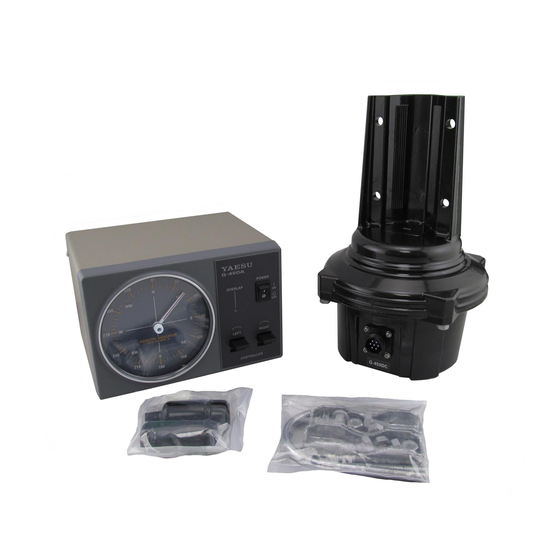
Summary of Contents for Yaesu G-450ADC
- Page 1 G-450ADC G-450CDC Antenna Rotator & Controller User Manual...
- Page 2 M8 x 16 Bolts ..........4 User Manual ...........1 Hex. Nuts ..........4 Specifications Rotation Torque: 600 kgf-cm (43 ft-lbs.) (@ AC 117 V: G-450ADC) 600 kgf-cm (43 ft-lbs.) (@ AC 230 V: G-450CDC) Braking Torque: 3000 kgf-cm (217 ft-lbs.) Maximum Vertical load:...
- Page 3 48 mm and 50 mm (1.89” to 1.97” O.D.). If it is necessary to use a mast of di- ameter less than 48 ~ 50 mm, nearly centered rotation can be achieved using the “GL-33” mast adjustment plate (Not supplied with G-450ADC), per the illustrations below. Mast Diameter φ32 to φ38: Use two plates.
- Page 4 Indicator needle adjustment potentiometer Overlap LED adjustment potentiometer Rotor control interconnection jack Fuse holder This holder requires a 1 A (G-450ADC) or 0.5 A (G-450CDC) fuse. If the fuse is blown, replace only with a fuse of the same rating.
- Page 5 Rotator Unit Components and Dimensions Rotator Unit Flat washer Spring washer Hexagonal nut U bolts Clamps φ186 Rotator Attachment Plate Dimensions φ9 (4 locations) The tower plate onto which the rotator unit is mounted must be drilled with four holes of 9 mm diameter, equally spaced on a circle of 119 mm diameter.
- Page 6 The following pages describe typical antennas which are acceptable for installation with the G-450ADC/-450CDC. The discussion below assumes maximum wind speeds of 30 meters per second (67 mph/108kph), and it is recommended that you include a safety margin of at least 30 % to account for higher wind gusts or other factors which might potentially cause damage to your installation.
- Page 7 The antenna system Wind Loading Area is: 0.3 m + 0.45 m = 0.75 m The Wind Loading Area and “K” factor are within the specifications for the G-450ADC/ -450CDC. Table 1: Wind Loading Areas for Common Antennas (Typical) Band...
- Page 8 Although C-25MWP and C-40MWP are 6 core cables, only 4 cores are used with the G-450ADC/-450CDC. 1. Disassemble the supplied round plug: slide off the rubber boot, remove the setscrew from the shell using a small screwdriver, then unscrew the shell from the plug. Save the setscrew in a safe place until step 10, so you don’t lose it.
- Page 9 20 mm 4 mm 8.6 ~ 10.5 mm Crimp with crimping tool or a pair of pliers Insert to the fullest extent Assembly of 6-pin Plastic Connector Tin the wires with solder Make sure to insert the Water Resist Boot first Terminal 1, 6 and 7 are not used.
- Page 10 Mounting the Rotator and Antenna Indoor Performance Check and Alignment 1. Temporarily connect the rotator unit and the controller using the connection cable prepared per the previous section. 2. Check to be sure that the POWER switch on the controller is set to OFF, then plug the con- troller’s AC cable into your station’s AC outlet.
- Page 11 Mounting the Rotator and Antenna 0° G-450A POWER OVERLAP AZIMUTH INDICATOR EACH DIVISION 5ー LEFT RIGHT CONTROLLER Indicator needle adjustment screw Figure 1 Adjustment potentiometer selection switch Indicator needle adjustment potentiometer Overlap LED adjustment potentiometer Figure 2...
- Page 12 It is recommended that the tips of the bolts be lightly dipped in lubri- cating grease, to ease disassembly in the future. 2. If a thrust bearing (such as the optional Yaesu model GS-065) is to be utilized, mount it on the top of the tower (see Figure 4) using the supplied hardware.
- Page 13 Mounting the Rotator and Antenna Mast Bearing GS-065 (option) Must be parallel Spring Washer M8 x 16 (length: 16 mm) Figure 3 Figure 4 Antenna Mast Figure 5 Figure 6 Mast Bearing Less than 1 m Provide GS-065 (option) sufficient slack More than 1 m Figure 7 Figure 8...
- Page 14 The control cable attached to this rotator could, in the event of a nearby or direct light- ning strike, carry lethal voltages down the cable and into your home. Yaesu strongly rec- ommends the installation of suitable lightning arrestors on all control cables and coaxial lead-in cables from your antenna installation.
- Page 15 The controller does not turn on. m Is the fuse blown out? Replace the 1 A (G-450ADC) or 0.5 A (G-450CDC) fuse in the fuse holder on the back of the controller after finding the cause and making corrections. CAUTION! Only replace with a similar type and rating 1 A fuse for G-450ADC, or 0.5 A for G-450CDC.
- Page 16 Limited Warranty is valid only in the country/region where this product was originally purchased. On-line Warranty Registration: Thank you for buying YAESU products! We are confident your new radio will serve your needs for many years! Please register your product at www.yaesu.com - Owner’s Corner Warranty Terms:...
- Page 17 2. Include proof of original purchase from an authorized YAESU dealer/distributor, and ship the product, freight prepaid, to the address provided by the YAESU Service Center in your country/ region. 3. Upon receipt of this product, returned in accordance with the procedures described above, by the YAESU Authorized Service Center, all reasonable efforts will be expended by YAESU MUSEN to cause this product to conform to its original specifications.
- Page 18 Safety Precautions (Be Sure to Read) Yaesu is not liable for any failures or problems caused by the use or misuse of this product by the purchaser or any third party. Also, Yaesu is not liable for damages caused through the use of this product by the purchaser or any third party, except in cases where ordered to pay damages under the laws.
- Page 19 Disposal of Electronic and Electrical Equipment Products with the symbol (crossed-out wheeled bin) cannot be disposed as household waste. Electronic and Electrical Equipment should be recycled at a facility ca- pable of handling these items and their waste by-products. Please contact a local equipment supplier representative or service cen- ter for information about the waste collection system in your country.
- Page 20 Copyright 2019 YAESU MUSEN CO., LTD. All rights reserved. No portion of this manual may be reproduced without the permission of YAESU MUSEN CO., LTD. YAESU MUSEN CO., LTD. Tennozu Parkside Building 2-5-8 Higashi-Shinagawa, Shinagawa-ku, Tokyo 140-0002 Japan 1907V-AS YAESU USA Printed in Japan 6125 Phyllis Drive, Cypress, CA 90630, U.S.A.
Need help?
Do you have a question about the G-450ADC and is the answer not in the manual?
Questions and answers