Advertisement
Quick Links
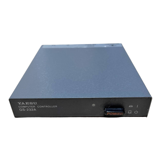
GS-232A
Computer Control Interface
for Antenna Rotators
YAESU MUSEN CO., LTD.
4-8-8 Nakameguro, Meguro-Ku, Tokyo 153-8644, Japan
YAESU U.S.A.
17210 Edwards Rd., Cerritos, CA 90703, U.S.A.
YAESU EUROPE B.V.
P.O. Box 75525 1118 ZN, Schiphol, The Netherlands
YAESU UK LTD.
Unit 12, Sun Valley Business Park, Winnall Close
Winchester, Hampshire, SO23 0LB, U.K.
YAESU GERMANY GmbH
Am Kronberger Hang 2, D-65824 Schwalbach, Germany
YAESU HK LTD.
11th Floor Tsim Sha Tsui Centre, 66 Mody Rd.,
Tsim Sha Tsui East, Kowloon, Hong Kong
Advertisement

Related Manuals for Yaesu G-1000DXA


Summary of Contents for Yaesu G-1000DXA
- Page 1 GS-232A Computer Control Interface for Antenna Rotators YAESU MUSEN CO., LTD. 4-8-8 Nakameguro, Meguro-Ku, Tokyo 153-8644, Japan YAESU U.S.A. 17210 Edwards Rd., Cerritos, CA 90703, U.S.A. YAESU EUROPE B.V. P.O. Box 75525 1118 ZN, Schiphol, The Netherlands YAESU UK LTD.
- Page 3 Firmware on the GS-232A supports either direct keyboard control, or commands from programs written specifically to support it (software is not supplied by Yaesu). In addition to reading and setting antenna angle and rotation speed, the firmware includes clocked positioning routines to auto-...
-
Page 4: Connector Pinouts
ENERAL Power Requirements: DC 12 V, 110 mA Case Size: 110 (W) x 21 (H) x 138 (D) mm Weight (approx.): 380 g Semiconductors Microprocessor: HD6303XP ROM: 27C64 RAM: 6264 A/D Converter: HD46508PA (10 bits) Serial Comms: 3-wire Async. DCE RS-232C voltage levels, 150 to 9600 baud, 8 data bits, 1 stop bit, no parity, no handshake... -
Page 5: Supplied Accessories
Control cable for the A Rotator (“Dual 5-pin” 1 “DIN” cable) r DC cable w/coaxial plug ... 1 pc r Hook & loop fasteners (for mounting) ... 1 pc ø1: G-5400B-G-5600B/G-5500 ø2: G-800DXA/G-1000DXA/G-2800DXA & G-800DXC/G-1000DXC/G-2800DXC ø1 GX-500 ... 1 pc ( GS-232A version ) ø2... -
Page 6: Power & Control Connections
During installation, a personal computer with a serial port and terminal software is required to calibrate trimmers on the Controller and on the Control Interface. Any simple in- teractive terminal program can be used - it only has to trans- mit keystrokes as typed, and display characters received from the GS-232A. - Page 7 G-5400B/-5600B Az-E Rotator r Connect the supplied DC cable to a source of 12 VDC. The red lead connects to the Positive (+) DC terminal, and the black lead connects to the Negative ( –) DC t e r mi n a l . The GS-232A requires 110 mA.
- Page 8 SDX Series Azimuth Rotator r Prepare the optional C-1000 Connection Cable. r Remove the Top cover from the controller. r Connect the 8-pin connector of the C-1000 Connection cable to the exposed 8-pin connector located the rear left corner in the controller. r Route the 5-pin connector of the C-1000 Connection cable through out the rubber grommet on the rear panel of the controller, and connect it to the AZ connector on...
- Page 9 r With the computer switched off, connect the RS-232C cable to the serial port of the computer, then connect the other end of your serial cable to the RS-232C connec- tor on the rear panel of the GS-232A. Only three wires are used for serial control, so there is no hardware hand- shaking.
- Page 10 Azimuth Offset Null r Before calibrate the Rotator, check to see that the GS- 232A’s DIP switch (switch 5) must be “ON” position. r From the Controller panel, set the Rotator fully counter- clockwise (set to 0°). r Press [ O ] Ž [ ] (the letter “oh”, and “E computer keyboard to activate the azimuth calibration routine.
- Page 11 Azimuth Offset Null r Before calibrating the Rotator, check to see that the GS- 232A’s DIP switch (switch 5) is set to the “OFF” posi- tion. r From the Controller panel, set the Rotator fully counter- clockwise (set to 180°). r Press [ O ] Ž...
- Page 12 Azimuth Offset Null r Before calibrating the Rotator, check to see that the GS- 232A’s DIP switch (switch 5) is set to the “OFF” posi- tion. r From the Controller panel, set the Azimuth Rotator fully counter-clockwise (set to 180°). r Press [ O ] Ž...
- Page 13 G-5400B/-5600B A Elevation Offset Null r From the Controller panel, set the Elevation Rotator to the “left” horizon (down, set to 0°). r Press [ O2 ] Ž [ ] (the letter “oh,” “2,” and “E the computer keyboard to activate the elevation calibra- tion routine.
- Page 14 Azimuth Offset Null r Before calibrating the Rotator, check to see that the GS- 232A’s DIP switch (switch 5) is set to the “ON” posi- tion. r From the Controller panel, set the Rotator fully counter- clockwise (set to 0°). r Press [ O ] Ž...
- Page 15 Elevation Offset Null r From the Controller panel, set the Elevation Rotator to the “left” horizon (down, set to 0°). r Press [ O2 ] Ž [ ] (the letter “oh,” “2,” and “E the computer keyboard to activate the elevation calibra- tion routine.
- Page 16 Elevation Offset Null r From the Controller panel, set the Elevation Rotator to the “left” horizon (down, set to 0°). r Press [ O2 ] Ž [ ] (the letter “oh,” “2,” and “E the computer keyboard to activate the elevation calibra- tion routine.
- Page 17 (not sup- plied by Yaesu). For brief summaries of the commands rec- ognized by the Control Interface, press [ H ] Ž [ ] for a list of azimuth commands, or [ H2 ] Ž...
- Page 18 In the following command descriptions, the elevation ver- sion of each command, where there is one, is shown in pa- rentheses (but don’t type the parentheses). Remember that elevation commands require the G-5400B, G-5600B or G- 5500 A Rotators, or the GX-500 adapter and the G- 500 or G-550 Elevation Rotator.
- Page 19 Maaa Turn to aaa degrees azimuth, where aaa is three digits be- tween “000” and “360 or 450: vary according to con- troller type.” Rotation starts. Msss aaa bbb ccc This command, together with the [ T ] command, provides automatic, timed tracking of moving objects or propagation by the Control Interface itself.
- Page 20 Elevation Control Commands These commands are only for az-el operation. Note that an azimuth angle must always be supplied when changing el- evation, and that a setting point consists of a pair of angles. Waaa eee Turn to aaa degrees azimuth and eee degrees elevation, where aaa is three digits between “000”...
- Page 21 Returned by [ H ] Command: --------- - COMMAND LIST 1 --------- - Clockwise Rotation Counter Clockwise Rotation CW/CCW Rotation Stop Antenna Direction Value Antenna Direction Setting. MXXX Time Interval Direction Setting. MTTT XXX XXX XXX - - - (TTT = Step value) (XXX = Horizontal Angle) Start Command in the time interval direction setting mode.
- Page 24 Copyright 2000 Yaesu Musen Co., Ltd. All rights reserved. No portion of this manual may be reproduced without the permission of Yaesu Musen Co., Ltd. Printed in Japan...
Need help?
Do you have a question about the G-1000DXA and is the answer not in the manual?
Questions and answers