Table of Contents
Advertisement
Quick Links
Warning:
•
Read this guide thoroughly before installation.
•
Operation personnel must wear proper personal protective equipment (PPE).
•
Ensure that AC and DC wires are not live before any connection work.
•
Adhere to the applicable codes and regulations of the installation site.
•
Hoymiles is not liable for damages resulting from improper installation and use.
Application
The HMS-500W-1T series microinverters are designed for mini PV systems in spaces like balconies and open areas, with three configuration options:
•
Single microinverter, one PV module, one HMS Field Connector, and an AC cable (installer-prepared).
•
Single microinverter, one PV module, and an HMS Plug and Play Cable.
•
Multiple microinverters, multiple PV modules, and HMS Cable System.
*:The AC cable's voltage range should be greater than 300 V. For proper installation, consider an AC Cable rated at 450/700 V, as recommended by Hoymiles. Be sure your selection complies with local wiring regulations.
Preparation
1
Check the Tools
2-9 N•m
Electrical
PPE
Screwdriver
2
Plan the Microinverters
• For single-microinverter systems, the entire system consists of one microinverter and one PV module.
• For multi-microinverter systems, define the number of microinverters per AC output line based on the
ampacity of the AC cables. (*
Model
HMS-300W-1T
2.5 mm²
18
Mechanical Installation & DC Side Electrical Installation
1
Attach the Microinverter to the Bracket
a. Follow the manufacturer's instructions to assemble the bracket.
b. Attach the microinverter (label side up) to the bracket, ensuring
the microinverter is properly aligned.
c. Secure the microinverter to the bracket with M8 screws (Torque:
9 N•m). Do not over-torque.
Warning:
• Check the balcony railing for its stability, weight capacity, and a smooth, level surface for bracket
attachment.
• Always place the microinverter beneath the PV module to avoid direct exposure to rain, UV, and other
harmful weather events.
• Allow 2 cm of space around the microinverter for ventilation and heat dissipation.
• The AC cables already include earth wires for direct grounding. Use the grounding clamps as shown on the guide if external grounding is required.
2
Complete the Installation Map
a. Peel off the microinverter's
removable SN label.
b. Affix the label to the respective
location on the installation map.
01
Balcony Reference
Diagonal
M8 Screws
Cable Tie
Cutter
AC cable ampacity determines the limits, which may vary. Check local codes for the actual limitations.
HMS-350W-1T
HMS-400W-1T
15
13
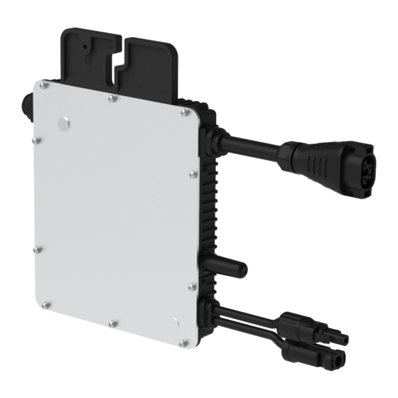
HMS-500W-1T Series Microinverter Quick Installation Guide
Danger:
•
This installation must be carried out with all devices off the grid.
•
To avoid damaging the microinverter or potential fire hazards, ensure all terminals
are securely tightened with the correct torque.
Notice:
Operating voltage: 230 V Single-phase and 230/400 V Three-phase grid.
Copper Wire*
8-9.5 mm
Copper Wire*
≤16.5 mm
(optional)
1.5-3 N•m
2.5/4/6 mm²
Wire
Torque
Crimping
Stripper
Wrench
Tool
HMS-450W-1T
12
3
Connect the PV Modules
a. Mount the PV modules above the microinverters.
b. Connect the DC leads of PV modules to the
corresponding DC inputs on the microinverters.
* Applicable for HMS-300W/350W/400W/450W/500W-1T Microinverters
Open Area Reference
3
Download the Application
HMS Disconnect
Tool
)
HMS-500W-1T
11
Label Side
Region: Global AP040884 REV1.1 © 2023 Hoymiles Power Electronics Inc.
S-Miles Installer
Mounting Torque: 9 N·m
label side
Torque: 2 N·m
-
-
+
+
-
-
+
+
-
-
+
+
-
-
+
+
Advertisement
Table of Contents

Related Manuals for Hoymiles HMS-500W-1T Series


Summary of Contents for Hoymiles HMS-500W-1T Series
- Page 1 ≤16.5 mm (optional) *:The AC cable's voltage range should be greater than 300 V. For proper installation, consider an AC Cable rated at 450/700 V, as recommended by Hoymiles. Be sure your selection complies with local wiring regulations. Preparation Check the Tools Download the Application 1.5-3 N•m...
- Page 2 Quantity depends on the on-site situation. Click Obstacle Scenario If you need to space microinverters farther apart due to an obstacle, Hoymiles offers two solutions: • Using an HMS Extension Connector to connect two HMS Connection Cables into a longer one.
- Page 3 • Using a longer HMS Connection Cable: Hoymiles offers cable lengths including 1.1 m, 2.0 m, 2.3 m, 3.0 m, and 4.6 m. If you require a different length, contact Hoymiles sales. Functions * To disconnect the HMS Extension Tighten/Loosen nuts in the AC Trunk...
- Page 4 Plants Plant Information Add Owner Bind Devices Installation Map Note: Consult the Microinverter User Manual and S-Miles Cloud Guide for comprehensive instructions on configuring your monitoring system. info@hoymiles.com sales@hoymiles.com service@hoymiles.com Region: Global AP040884 REV1.1 © 2023 Hoymiles Power Electronics Inc.
Need help?
Do you have a question about the HMS-500W-1T Series and is the answer not in the manual?
Questions and answers