Table of Contents
Advertisement
Quick Links
Advertisement
Table of Contents

Related Manuals for Friedrich DSSXEMWRT3


Summary of Contents for Friedrich DSSXEMWRT3
- Page 1 DSSXEMWRT3 VRPXEMWRT3 EMWRT3 Wireless Energy Management Network- Capable Thermostat with Built-in Occupancy Sensor and HVAC Controller INSTRUCTION MANUAL PTAC Direct Sales, Inc. 185 S. Kimball Ave., Revision of March 1st, 2023 Suite 130 Southlake, TX 76092 877.454.7822 (T)
-
Page 2: Table Of Contents
Table of Contents How to use this manual..................6 Introduction.....................7 SKUs Referenced in this Manual ...............8 Equipment Nomenclature ................9 Installation Considerations ................10 General: Network Installation .................11 Notice ......................11 Connecting the Antenna Module ..............12 Connecting the Ethernet Cable ..............13 Powering on the Server .................14 Configuring the Online Connection Kit............15 General: HVAC Controller Installation .............16 Introduction ....................16... - Page 3 Configuring the Functionality of a Sensor ............35 Completing the Sensor Setup ................36 DSS: Unit Specific Installations ................37 Installing the HVAC Controller in Friedrich Ductless Split Systems.....37-38 DSS: Thermostat Configuration..............39 VRP: Unit Specific Installations ................40 Installing the Wireless Receiver on a VRP Unit..........40 Mouting the Wall Controller of the VRP to the Wall........41...
- Page 4 Table of Contents General: Vert-I-Pak / PTAC T-stat Installation..........47-48 General: Custom Energy Savings Settings ............49 Accessing the Custom Energy Savings Settings..........49 Using the Thermostat Settings Screens ............51 Custom Energy Settings Index ..............51-52 01 – FAN CONTROL MODE ..................53 02 – 1 STAGE DIFFERENTIAL - HEAT ..............
- Page 5 Table of Contents 31– DOOR/WINDOW SHUT OFF RELAY..............83 32– AUTO FAN SPEED 1ND STAGE DIFFERENTIAL.............84 33– AUTO FAN SPEED 2ND STAGE DIFFERENTIAL.............85 34 – TEMPERATURE CALIBRATION ................86 35 – AUTOMODE TYPE ................... 87 36 – HUMIDITY CONTROL IN AN OCCUPIED ROOM ..........88 37 –...
-
Page 6: How To Use This Manual
How to use this manual This manual is written to help you mount, install and configure the next units: • • • FreshAire PTAC • Vert-I-Pak / PTAC units Common settings and instructions for the above units will be listed in the “General”... -
Page 7: Introduction
Introduction Friedrich Energy Management Thermostats deliver unprecedented energy savings without compromising the comfort of occupants. An Integrated occupancy sensor uses a combination of motion and thermal sensing technologies for accurate occupancy detection. Reliable occupancy detection allows for energy savings when rooms are unoccupied. -
Page 8: Skus Referenced In This Manual
SKUs Referenced in this Manual This user guide includes instructions on how to install each of the following compatible SKUs. Product SKU(s) Description Type DSSXEMWRT3 Networked Friedrich Wireless Thermostat with HVAC Thermostats VRPXEMWRT3 Controller EMWRT3 EMRWOS3 Occupancy Sensor EMRWDS3 Door/Window Switch with reed magnets... -
Page 9: Equipment Nomenclature
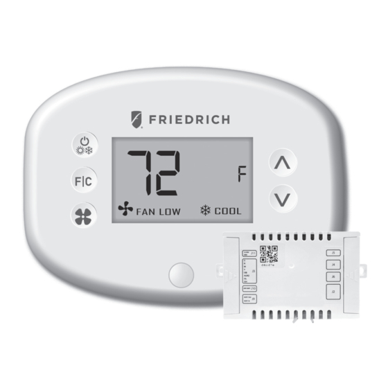
Introduction Equipment Nomenclature Before you begin installing Friedrich equipment, familiarize yourself with the various components that may be included in your shipment. Thermsotat & Wireless Receiver Online Connection Kit Occupancy Sensor Door/Window Sensor Temperature Sensor... -
Page 10: Installation Considerations
Installation Considerations Selecting the appropriate installation location of the thermostat and any accessories is crucial to the proper operation of your Friedrich energy management system. The following guidelines should be adhered to in all cases; THE THERMOSTAT’S OCCUPANCY SENSOR SHOULD FACE THE BED AREA OF THE ROOM OR THE AREA WHERE THE OCCUPANT WILL SPEND THE MOST TIME. -
Page 11: General: Network Installation
General: Network Installation NOTICE TO ENABLE NETWORKING CAPABILITIES OF THE FRIEDRICH THERMOSTAT, REFER TO THE “NETWORK INSTALLATION” SECTION OF THIS MANUAL. BEFORE STARTING THE INSTALLATION OF THE NETWORKED THERMOSTATS, ENSURE THAT THE ONLINE CONNECTION KIT IS CONNECTED TO THE INTERNET. -
Page 12: Connecting The Antenna Module
General: Network Installation Connecting the Antenna Module • Screw the Antenna onto the Wireless Receiver; • Connect the Wireless Receiver to the Server using the supplied USB cable; • Affix the Wireless Receiver to the wall with double sided adhesive tape; •... -
Page 13: Connecting The Ethernet Cable
General: Network Installation Connecting the Ethernet Cable To Internet Router/Switch • Connect the Server to the LAN port with the supplied RJ-45 cable. -
Page 14: Powering On The Server
General: Network Installation Powering on the Server To Internet Router/Switch To Power supply • Plug the Server into an electrical outlet with the supplied power cord. TO PREVENT POWER RELATED ISSUES, PLUG THE SERVER INTO A UPS (UNINTERRUPTED POWER SUPPLY) UNIT. -
Page 15: Configuring The Online Connection Kit
General: Network Installation Configuring the Online Connection Kit • Ensure the Online Connection Kit is receiving an IP from a DHCP server. A public IP will not work; • Ensure that the MAC address is properly Whitelisted if it needs to bypass a login (splash) page to be able to reach the internet. -
Page 16: General: Hvac Controller Installation
General: HVAC Controller Installation Introduction Friedrich HVAC Controllers enable wireless thermostat control of most HVAC units. The illustration below indicates the various ports available on the HVAC Controller. Refer to the appropriate page in this manual for wiring instructions for your specific HVAC unit. -
Page 17: Installing The Hvac Controller In 24Vac Relay Units
General: HVAC Controller Installation Installing the HVAC Controller in 24VAC Relay Units • Power Off the HVAC unit; • Mount the HVAC Controller inside of the HVAC unit; • Use the supplied wire harness to connect the HVAC Controller to the HVAC unit;... -
Page 18: Using The Hvac Controller To Power A Wireless Thermostat (Optional)
General: HVAC Controller Installation Using the HVAC Controller to Power a Wireless Thermostat (Optional) The J11 port on the HVAC Controller may be used to supply 12VDC power to a wireless thermostat, if desired. • Use the supplied wire harness to connect the J11 port to the back of the wireless thermostat 12VDC Output (J11 Port) -
Page 19: Using The Hvac Controller's Dry Contacts To Control External Devices
A jumper on J10 will make this a “wet” contact supplying power from R&C. • For PTAC connection, connect the low voltage wires to screw terminals on the PTAC unit low voltage terminal block - refer to the wiring diagram below. Friedrich HVAC CONTROLLER From 110VAC Breaker XFMR 01 FCU/VTAC/PTAC... -
Page 20: General: Thermostat Installation
General: Thermostat Installation Mounting the Thermostat to the Wall • Select the appropriate installation location for the thermostat, taking into account the following; THE THERMOSTAT’S OCCUPANCY SENSOR SHOULD FACE THE BED AREA OF THE ROOM OR THE AREA WHERE THE OCCUPANT WILL SPEND THE MOST TIME. -
Page 21: General: Sensor Installation
General: Sensor Installation Mounting a Remote Wireless Sensor (Optional) • Select the appropriate installation location for the external sensor, taking into account the following; OCCUPANCY SENSORS SHOULD FACE THE DESIRED OCCUPANCY DETECTION AREA. • With the faceplate removed, place the sensor on the wall in the installation location and mark location for drilling holes for the two (2) mounting screws;... -
Page 22: General: Thermostat Configuraton
General: Thermostat Configuration Understanding the Thermostat Screen Disconnected sensor How to fix it: • Check sensor’s batteries • Check sensor’s distance or if there is any large metal obstacle Note: the d icon will disappear within 5min if new batteries are inserted and within 60 minutes if distance or metal obstacles issues Wireless connection are resolved. -
Page 23: Configuring The Thermostat
General: Thermostat Configuration Configuring the Thermostat Prerequisites: During the installation training with your support agent you will be provided with: Mesh ID (provided by Verdant Support), Room Number, Time, Equipment Code. To start with the configuration process, remove the faceplate of the thermostat and insert 2 AA batteries. -
Page 24: Pairing The Thermostat And The Hvac Controller
General: Thermostat Configuration Pairing the Thermostat with the HVAC Controller Each wireless thermostat must be paired with an individual HVAC Controller during installation. The thermostat will search for the closest HVAC Controller to it and display the unique HVAC Controller ID. The HVAC Controller ID is located on the case of the HVAC Controller. -
Page 25: Setting The Mesh Id
General: Thermostat Configuration Setting the MESH ID For networked installations, a unique MESH ID is associated to each Online Connection Kit and is provided by your technical support agent during the installation training (can also be found labeled on the device). For properties using a single Online Connection Kit, each thermostat may be linked to MESH ID 0001. -
Page 26: Entering The Room Number
General: Thermostat Configuration Entering the Room Number Enter the room number by changing the characters on the screen. Available characters include digits 0-9 and letters A-F. To distinguish between two or more thermostats in the same unit, enter as follows: Thermostat 1: 00100 Thermostat 2: 0100A ➤... -
Page 27: Configuring The Equipment Settings
General: Thermostat Configuration Configuring the Equipment Settings Enter the equipment code by changing the digits on the screen. Refer to the table below. • Press the FAN button to advance to the next equipment setting. • Press the UP and DOWN buttons to increase or decrease the value; •... -
Page 28: Equipment Codes
General: Thermostat Configuration Equipment codes Model description Equipment code FreshAire 12V Control* 6613 6643 6603 Heat Pump PTAC/VTAC with a reversing valve B and electric Heat 1112 with two fan speeds FreshAire PTAC 24V Control* 1012 * PTAC PVH models can connect either AC or DC control wiring: PVH that finishes in -A connects to 24 V and runs with equipment code 1012;... -
Page 29: Configuring Energy Savings Settings
General: Thermostat Configuration Configuring the Energy Saving Settings • Press the UP and DOWN buttons to increase or decrease the energy savings preset. • Press the F|C button to advance to the next menu. Preset Energy Savings Presets E-0* Energy Savings Off - No Temperature Setback Lowest Energy Savings Lower Energy Savings Standard Energy Savings... -
Page 30: Setting The Thermostat Clock
General: Thermostat Configuration Setting the thermostat clock HOURS MINUTES Set the thermostat clock to current time in 24h (Military Time) format. • Press the FAN button to advance to the next digit; • Press the UP and DOWN buttons to increase or decrease the digits •... -
Page 31: Testing The Thermostat
General: Thermostat Configuration Testing the Thermostat Following the thermostat configuration, test if the thermostat is controlling the HVAC unit. • Ensure the thermostat is powered and the faceplate is on. • Press the DOWN button to change the temperature set point below the current room temperature to confirm that the thermostat initiates air conditioning;... -
Page 32: General: Configuration & Managing Accessories
General: Configuring & Managing Accessories Activating a Sensor • Remove the faceplate from the thermostat and the sensor(s) to be paired in the room; • Insert two (2) AAA-cell battery into each sensor (not supplied); • Press the button inside the sensor to make the sensor discoverable; •... -
Page 33: Paring A Sensor
General: Configuring & Managing Accessories Pairing a Sensor Once the thermostat and HVAC unit are powered and the thermostat faceplate is removed, follow the sensor configuration instructions to correctly configure the sensors. • Press and hold the config button on the thermostat to get to the Mesh ID screen. -
Page 34: Verifying Sensor Connection Status And Unlinking Sensors
General: Configuring & Managing Accessories Verifying Sensor Connection Status and Unlinking Sensors With the thermostat and HVAC unit powered; • Remove the faceplate from the thermostat • Press and hold the config button until the MESH ID appears on the screen; •... -
Page 35: Configuring The Functionality Of A Sensor
General: Configuring & Managing Accessories Configuring the Functionality of a Sensor The thermostat allows the user to choose the functionality of a sensor. Use the table below to configure the desired functionalities. For example, if sensor is intended to be used as Occupancy Sensor, OCC value must be set to 1. •... -
Page 36: Completing The Sensor Setup
General: Configuring & Managing Accessories Completing the Sensor Setup The thermostat will countdown from thirty (30) seconds. If the sensor has successfully paired, the thermostat will display SUCC. If the sensor did not pair successfully, the display will read FAIL, and the process must be repeated. •... -
Page 37: Dss: Unit Specific Installations
DSS: Unit Specific Installations Installing the HVAC Controller in Friedrich Ductless Split Systems for use with Friedrich Wifi capable Floating Air Pro/Premier Wall mounted or Cassette units. ➤ Power Off the HVAC Unit; ➤ Mount the wireless HVAC Controller on the top of the indoor HVAC unit;... - Page 38 DSS: Unit Specific Installations Installing the HVAC Controller in Friedrich Ductless Split Systems for use with Friedrich Wifi capable Floating Air Pro/Premier Wall mounted or Cassette units. ➤ ➤ Disconnect the wifi module in the DSS Friedrich Pro/Premier Wall mount/ Cassette and connect to wireless card using the other end of the wire harness;...
-
Page 39: Dss: Thermostat Configuration
DSS: Thermostat Configuration Configuring the Equipment Settings Enter the equipment code ‘6643’ by changing the digits on the screen. ➤ Press the FAN button to advance to the next equipment setting. ➤ Press the UP and DOWN buttons to increase or decrease the value; ➤... -
Page 40: Vrp: Unit Specific Installations
VRP: Unit Specific Installations Installing the Wireless Receiver on a VRP Unit ® Mount the Receiver as high as possible. It MUST be higher than the VRP unit (top) Placing the Wireless Receiver directly on the VRP unit is also acceptable. -
Page 41: Mouting The Wall Controller Of The Vrp To The Wall
VRP: Unit Specific Installations Mounting the Wall Controller of the VRP to the Wall ➤ Remove the Wall Controller cover; ➤ Use the supplied wall anchors and mounting screws to secure the Wall Controller to the wall; ➤ Insert two (2) AA-cell batteries (not-supplied) into the Wall Controller battery compartment;... -
Page 42: Installing The Hvac Controller In Vrp Unit
VRP: Unit Specific Installations Installing the HVAC Controller in VRP Unit ➤ Insert two supplied jumpers* into function selection pins 1-2, ➤ and 4-5 of J5 of the wireless HVAC controller. ➤ Connect the other end of the harness into the four VRP terminals. ➤... -
Page 43: Vrp: Thermostat Configuration
VRP: Thermostat Configuration Configuring the Equipment Settings for VRP Enter the equipment code ‘6603’ by changing the digits on the screen. ➤ Press the FAN button to advance to the next equipment setting. ➤ Press the UP and DOWN buttons to increase or decrease the value; ➤... -
Page 44: Freshaire Ptac: Unit Specific Installations
® ® Note: Friedrich FreshAire PTAC models with a SKU ending in ‘A’ are only compatible ® with 24V. Friedrich FreshAire PTAC models with a SKU ending in ‘B’ and above are ® compatible with VRPXEMWRT3 thermostat. • Connect one end of the Cat6 wire to the FreshAire PTAC using the RJ45 port ®... -
Page 45: Installing The Hvac Controller For Freshaire Ptac Unit
FreshAire PTAC: Unit Specific Installations Installing the HVAC Controller for FreshAire PTAC Unit ➤ Power Off the HVAC Unit; ➤ Mount the wireless HVAC Controller on the top of the indoor HVAC unit; ➤ Connect the one end of the supplied wire harness to the J4 port on the HVAC Controller;... -
Page 46: Freshaire Ptac: Thermostat Configuration
FreshAire PTAC: Thermostat Configuration Configuring the Equipment Settings Enter the equipment code ‘6613’ by changing the digits on the screen. ➤ Press the FAN button to advance to the next equipment setting. ➤ Press the UP and DOWN buttons to increase or decrease the value; ➤... -
Page 47: General: Vert-I-Pak / Ptac T-Stat Installation
• Ensure that the Friedrich HVAC Controller is secured and cannot fall into the PTAC/ Vert-I-Pak* unit Condensation Pan. • Plug in the PTAC/Vert-I-Pak* unit to power supply. - Page 48 General: Vert-I-Pak /PTAC T-stat Installation For wiring instructions, please see the table below: HVAC Controller 24VAC Relay Connections (J3 Port) J9 Port AUX1 Aux2 Black White Yellow Orange Brown Purple Green Blue Reverse Aux2 Common 24VAC Heat Cool Fan Low Fan High Valve Signal...
-
Page 49: General: Custom Energy Savings Settings
General: Custom Energy Savings Settings If you do not want to use one of the energy saving presets detailed in Appendix 1, you can enter the custom energy savings settings. Accessing the Custom Energy Savings Settings • Ensure the thermostat is powered and faceplate removed; •... -
Page 50: Using The Thermostat Settings Screens
General: Custom Energy Savings Settings Using the Thermostat Settings Screens SETTING VALUE SETTING INDEX • Use the “Up” and “Down” buttons to select the desired ‘index setting’. • Press the “Config” button to edit the value of the ‘index setting’; •... -
Page 51: Custom Energy Settings Index
General: Custom Energy Savings Settings Setting Index... - Page 52 General: Custom Energy Savings Settings Setting Index...
-
Page 53: Fan Control Mode
General: Custom Energy Savings Settings 01 – FAN CONTROL MODE Select Fan Control Mode: 00 * NON-Continuous - fan runs only when there is a demand for heating or air conditioning with auto adjustable fan speed; CONTINUOUS - fan runs continuously when thermostat is on Indicates default setting;... -
Page 54: St Stage Differential - Heat
General: Custom Energy Savings Settings 02 – 1 STAGE DIFFERENTIAL - HEAT 02-30 (0.2°F - 3.0°F; 0.5°F* default setting) Select the number of degrees the thermostat has to sense between the automatic changeover temperature for heat and the room temperature before a call for the 1st stage heating is initiated. -
Page 55: Nd Stage Differential - Heat
General: Custom Energy Savings Settings 03 – 2 STAGE DIFFERENTIAL - HEAT 10-20 (1.0°F - 2.0°F*; 2.0°F* default setting) Select the difference between 1st stage heating and 2nd stage heating initiation. This also applies as the 3rd and 4th stage differential on top of the 2nd when there are more than 2 stages. -
Page 56: 1St Stage Differential - Cool
General: Custom Energy Savings Settings 04 – 1ST STAGE DIFFERENTIAL - COOL 02-30 (0.2°F - 3.0°F; 0.5°F* default setting) Select the number of degrees the thermostat has to sense between the automatic changeover temperature for cool and the room temperature before a call for the 1st stage cooling is initiated. -
Page 57: Incidental Occupancy Threshold
General: Custom Energy Savings Settings 05 – INCIDENTAL OCCUPANCY THRESHOLD 00-60 (05* default setting) Select the minimum period of time (in minutes) for which occupancy needs to be detected to enter the guest occupancy mode. When occupancy is detected, thermostat will switch to occupied mode for a duration of “Incidental Occupancy Threshold”... -
Page 58: Night Occupancy Threshold
General: Custom Energy Savings Settings 06 – NIGHT OCCUPANCY THRESHOLD 00-60 (01* default setting) Select the minimum period of time (in minutes) for which occupancy needs to be detected in order to consider the room occupied during the “Night Occupancy”period. When occupancy is detected during the “Night Occupancy Period”... -
Page 59: Forced 2Nd Stage Heating
General: Custom Energy Savings Settings 07 – FORCED 2ND STAGE HEATING 00-60 (30* default setting) Select a number of minutes 1st stage heating will run before 2nd stage heating is automatically initiated if the guest set point is not reached and the 2nd stage heating is not initiated through differential settings. -
Page 60: Night Occupancy Start
General: Custom Energy Savings Settings 08 – NIGHT OCCUPANCY START 00-23 (21* default setting) Select the start time (in hours - 24-hour clock) for “Night Occupancy” If occupancy is detected for a period of time longer than the “Night Occupancy Threshold” during “Night Occupancy” period, the thermostat will disable the occupancy sensor and consider the room occupied until the end of the “Night Occupancy”... -
Page 61: Night Occupancy End
General: Custom Energy Savings Settings 09 – NIGHT OCCUPANCY END 00-23 (09* default setting) Select the time (in hours - 24-hour clock) for “Night Occupancy” to end. The time of day the “Night Occupancy” ends and the thermostat switches back to the room sensing settings chosen in the other occupancy modes. -
Page 62: Temperature Recovery Time
General: Custom Energy Savings Settings 10 – TEMPERATURE RECOVERY TIME 00-60 (25* default setting) Select the maximum time allowed for a HVAC unit to attain temperature as defined by Heat and Cool “Recovery Temperature”; “Temperature Recovery Time” selected here and the actual temperature recovery ability of the HVAC unit are used to calculate setback temperatures. -
Page 63: Recovery Temperature - Heat
General: Custom Energy Savings Settings 11 – RECOVERY TEMPERATURE - HEAT 62-82 (67°F* default setting) Select the room temperature in °F that a HVAC unit will have to attain within the selected “Temperature Recovery Time” when there is a need for heating. If recovery is disabled (“Temperature Recovery Time”... -
Page 64: Temperature Setback Delay
General: Custom Energy Savings Settings 12 – TEMPERATURE SETBACK DELAY 00-120 (20* default setting) Select the time delay (in minutes) for which the room that is in the guest occupancy mode needs to be unoccupied before the temperature setback is initiated. This feature prevents initiating temperature setback prematurely while the guest is still in the room but in an area where occupancy cannot be detected by the occupancy sensor. -
Page 65: Minimum Setback Temperature - Heat
General: Custom Energy Savings Settings 13 – MINIMUM SETBACK TEMPERATURE - HEAT 52-72 (64°F* default setting) Select the “Minimum Setback Temperature” in °F. Setback temperature is calculated by measuring HVAC unit’s ability to attain “Recovery Temperature - Heat” within “Temperature Recovery Time”. -
Page 66: Maximum Setback Temperature
General: Custom Energy Savings Settings 14 – MAXIMUM SETBACK TEMPERATURE 72-92 (78°F* default setting) Select the “Maximum Setback Temperature” in °F. Setback temperature is calculated by measuring HVAC unit’s ability to attain “Recovery Temperature - Cool” within “Temperature Recovery Time”. If recovery is disabled (“Temperature Recovery Time”... -
Page 67: Recovery Temperature - Cool
General: Custom Energy Savings Settings 15 – RECOVERY TEMPERATURE - COOL 62-82 (74°F* default setting) Select the room temperature in °F that a HVAC unit will have to attain within the selected “Temperature Recovery Time” when there is a need for air conditioning. -
Page 68: Minimum Set Point
General: Custom Energy Savings Settings 16 – MINIMUM SET POINT 64-84 (66°F* default setting) Select the minimum set point in °F that a guest can select. -
Page 69: Maximum Set Point
General: Custom Energy Savings Settings 17 – MAXIMUM SET POINT 60-82 (78°F* default setting) Select the maximum set point in °F that a guest can select. -
Page 70: Temperature Control Mode
General: Custom Energy Savings Settings 18 – TEMPERATURE CONTROL MODE Select Temperature Control Mode: MANUAL - Allows users to select HEAT only or COOL only temperature control mode to maintain the room temperature; 01 * AUTOMATIC - Thermostat automatically turns on heating or air conditioning to maintain the room temperature at the selected temperature set point;... -
Page 71: Auto Changeover Set Point Offset
General: Custom Energy Savings Settings 19 – AUTO CHANGEOVER SET POINT OFFSET 00-04 (01°F* default setting) Select the difference between the guest-selected set point and the heat and the cool set point when the thermostat is in the automatic temperature control mode. This value plus the 1st stage differential defined in steps 02 and 04, defines the temperature at which the thermostat would automatically change heating/cooling modes. -
Page 72: Setback Set Points
General: Custom Energy Savings Settings 20 – SETBACK SET POINTS When room is unoccupied and the thermostat is in the setback mode or turned off, it will NOT maintain the temperature between heat and cool setback set points; When room is unoccupied and the thermostat is in the setback mode or turned off, it will maintain the temperature between heat and cool setback set points. -
Page 73: Auto-Restore
General: Custom Energy Savings Settings 21– AUTO-RESTORE When guest enters the room, the thermostat will be turned off - it will not automatically restore the most recent guest settings; 01 * When guest enters the room, the thermostat will automatically restore the most recent guest settings;... -
Page 74: The Setting Is Reserved For The Internal Functions
General: Custom Energy Savings Settings 22 – The setting is reserved for the internal functions. -
Page 75: Setpoint Overshoot
General: Custom Energy Savings Settings 23 – SETPOINT OVERSHOOT 04-20 (0.6°F* default setting) Select the °F of overshoot above or below the setpoint on the thermostat before the thermostat stops the call for cooling or heating. -
Page 76: Automatic Humidity Control
General: Custom Energy Savings Settings 24 – AUTOMATIC HUMIDITY CONTROL † 00 * Disable automatic humidity control; Enable automatic humidity control; When “Automatic Humidity Control” is enabled, thermostat will turn on air conditioning in an unoccupied room when humidity raises above 60% and room temperature is above 72°F until either room humidity is below 55% or room temperature is below 72°F;... -
Page 77: 2Nd Stage Cool Differential
General: Custom Energy Savings Settings 25 – 2ND STAGE COOL DIFFERENTIAL 05-30 (2.0°F* default setting) Select the °F differential required to trigger 2nd stage cooling (). This also applies as the 3rd and 4th stage differential on top of the 2nd when there are more than 2 stages. -
Page 78: Smart Setback
General: Custom Energy Savings Settings 26 – SMART SETBACK 00 * Smart Setback disabled; Smart Setback enabled; Smart setback reduces the excessive heating or cooling that may occur when occupants set their thermostats to setpoints outside of the norm. Occupant setpoint that is greater than Cool Setback or less than Heat Setback will be respected during setbacks to save energy. -
Page 79: Humidity Control Threshold
General: Custom Energy Savings Settings 27 – HUMIDITY CONTROL THRESHOLD 55-70 (60* default setting) Select the relative humidity level that automatic humidity control will attempt to control for in conjunction with the humidity cut-off temp. -
Page 80: Humidity Cutoff Temperature
General: Custom Energy Savings Settings 28 – HUMIDITY CUTOFF TEMPERATURE 65-75 (72°F* default setting) Select the temperature at which humidity control will shut off. -
Page 81: The Setting Is Reserved For The Internal Functions
General: Custom Energy Savings Settings 29– The setting is reserved for the internal functions. -
Page 82: Energy Management On/Off
General: Custom Energy Savings Settings 30– ENERGY MANAGEMENT ON/OFF Energy management disabled; 01 * Energy management enabled. Indicates default setting;... -
Page 83: 31- Door/Window Shut Off Relay
General: Custom Energy Savings Settings 31– DOOR/WINDOW SHUT OFF DELAY 01-60 (2* default setting) Select the time delay (in minutes) before the thermostat disables air conditioning when a door or window sensor has been installed. -
Page 84: 32- Auto Fan Speed 1Nd Stage Differential
General: Custom Energy Savings Settings 32– AUTO FAN SPEED 1ST STAGE DIFFERENTIAL 02-08 (2°F* default setting) Select the °F differential between Low Fan and 2nd stage fan (Medium or High) when Auto-Fan Speed is selected. -
Page 85: 33- Auto Fan Speed 2Nd Stage Differential
General: Custom Energy Savings Settings 33– AUTO FAN SPEED 2ND STAGE DIFFERENTIAL 02-10 (4°F* default setting) Select the °F differential between Medium and High Fan when Auto-Fan Speed is selected (only active if 3 fan speeds are available). -
Page 86: Temperature Calibration
General: Custom Energy Savings Settings 34 – TEMPERATURE CALIBRATION -5.0 – 5.0 (0.0°F* default setting) Calibrate the temperature display : -5.0°F - 5.0°F. -
Page 87: Automode Type
General: Custom Energy Savings Settings 35 – AUTOMODE TYPE Standard Auto Mode - The thermostat will apply the deadband on the guest setpoint and control temperature with the guest setpoint as the median; Changover Auto Mode - The thermostat will apply the deadband as a changeover limit where the deadband is crossed triggering a change in heating or cooling mode;... -
Page 88: Humidity Control In An Occupied Room
General: Custom Energy Savings Settings 36 – HUMIDITY CONTROL IN AN OCCUPIED ROOM Humidity control OFF - The thermostat will disable humidity control when the room is occupied; Humidity control ON - The thermostat will enable humidity control even when the room is occupied. -
Page 89: Heat Equipment Lockout
General: Custom Energy Savings Settings 37 – HEAT EQUIPMENT LOCKOUT Equipment lockout is disabled (default) - The thermostat will enable both compressor and electric heat; Compressor lockout - If set to 1, the Thermostat will only allow electric heat; Electric heat lockout - If set to 2, the Thermostat will only allow compressor heat. -
Page 90: General: Thermostat Maintenance
General: Thermostat Maintenance Replacing Thermostat Batteries The low battery indicator will be displayed on the thermostat screen when it is necessary to replace batteries in the thermostat. Under normal operating conditions, new brand-name alkaline batteries will last for a period of approximately eighteen (18) months. Please replace batteries every sixteen (16) months to ensure continuous thermostat operation. -
Page 91: General: Errors
General: Errors Errors that might appear Description Appearance The thermostat and HVAC controller are disconnected. Make sure the HVAC Controller is powered and Connectivity Symbol on the screen installed. Optimize antenna placement to ensure unhindered signal transmission around metallic barriers/obstacles. Door or Window is Open Close the Door/Window Low Battery... -
Page 92: General: Troubleshooting
If the master reset was successful, the thermostat will display SETUP after three (3) seconds and the thermostat must be re-configured. Refer to the thermostat configuration section of this manual. Contact Friedrich technical support if the issues are not resolved. -
Page 93: Appendix 1 - Energy Saving Presets
APPENDIX 1 - Energy Saving Presets Bolded values below indicate the factory default profile* Setting Level Level Level Level Level Level Index Fan Control Mode AUTO AUTO AUTO AUTO AUTO AUTO 1st Stage Differential Heat 2nd Stage Differential Heat 1st Stage Differential Cool Guest Occupancy Threshold Night Occupancy Threshold Force 2nd Stage Heating After... - Page 94 APPENDIX 1 - Energy Saving Presets Setting Level Level Level Level Level Level Index Setback Set Points Auto Restore N/A - reserved for internal function Setpoint Overshoot Automatic Humidity Control 2nd Stage Cool Differential Smart Setback Humidity Control Threshold Humidity Cutoff Temperature N/A - reserved for internal function Energy Management On/Off Door/Window Shutoff Delay...
-
Page 95: Appendix 2 - Glossary
APPENDIX 2 - Glossary “Automatic Fan Control Mode” - fan runs only when in order to enter the “Night Occupancy” mode; there is a demand for heating or cooling; “Night Occupancy Period” - The period of “Manual Fan Control Mode” - occupant can select time during the day during which the “Night between automatic or continuous fan operation;... -
Page 96: Warranty Information
Warranty Information For the most recent warranty information, please visit www.friedrich.com. -
Page 97: Technical Specifications
Technical Specifications Thermostat Product Type DSSXEMWRT3 SKU(s) VRPXEMWRT3 EMWRT3 Wireless Frequency 902-928MHz (NA) Case Dimensions (Imperial) 4.02 x 5.51” x 0.93” Case Dimensions (Metric) 102mm x 140mm x 23.5mm Screen Dimensions 3.63” x 2.13” (Imperial) Screen Dimensions (Metric) 92mm x 54mm Operating Voltage 2 1.5VDC AA Alkaline Non-rechargeable Batteries - Not Supplied... - Page 98 Technical Specifications HVAC Controller Gateway Product Type HVAC Controller for DSSXEMWRT3 EMOCT3 SKU(s) HVAC Controller for VRPXEMWRT3 HVAC Controller for FreshAire Wireless Frequency 902-928MHz (NA) Case Dimensions 4.08” x 2.76” x 1.02” 4.72” x 3.15” x 1.18” (Imperial) Case Dimensions (Metric) 104mm x 70mm x 26mm...
- Page 99 Technical Specifications Root Node Sensors Product Type EMRWOS3 EMRWTS3 SKU(s) Root Node for EMOCT3 EMRWDS3 Wireless Frequency 902-928MHz (NA) 902-928MHz (NA) Case Dimensions 2.4” x 1.54” x 0.78” 1.82” x 2.4” x 0.74” (Imperial) Case Dimensions 46mm x 61mm x 19mm 46mm x 61mm x 19mm (Metric) Screen Dimensions...
- Page 100 THIS DEVICE COMPLIES WITH PART 15 OF THE FCC RULES. OPERATION IS SUBJECT TO THE FOLLOWING TWO CONDITIONS: (1) THIS DEVICE MAY NOT CAUSE HARMFUL INTERFERENCE, AND (2) THIS DEVICE MUST ACCEPT ANY INTERFERENCE RECEIVED, INCLUDING INTERFERENCE THAT MAY CAUSE UNDESIRED OPERATION. THE MANUFACTURER IS NOT RESPONSIBLE FOR ANY RADIO OR TV INTERFERENCE CAUSED BY UNAUTHORIZED MODIFICATIONS TO THIS EQUIPMENT.
Need help?
Do you have a question about the DSSXEMWRT3 and is the answer not in the manual?
Questions and answers