Table of Contents
Advertisement
Quick Links
3550412A
215 Colonnade Road South, Ottawa, Ontario, Canada K2E 7K3
Tel: (613) 225-9531 • Fax: (613) 225-6965 • Canada & U.S. Toll Free: 1-800-465-5777
E-mail: support@armstrongmonitoring.com • Website: www.armstrongmonitoring.com
____________________________________________________________________________________
AMC-1BZX Gas Monitor
AMC-1BZX
Gas Monitor
USER MANUAL
The Armstrong Monitoring Corporation
1
Copyright ©, 2024 AMC
Advertisement
Table of Contents

Related Manuals for AMC AMC-1BZX


Summary of Contents for AMC AMC-1BZX
- Page 1 AMC-1BZX Gas Monitor AMC-1BZX Gas Monitor USER MANUAL 3550412A Copyright ©, 2024 AMC The Armstrong Monitoring Corporation 215 Colonnade Road South, Ottawa, Ontario, Canada K2E 7K3 Tel: (613) 225-9531 • Fax: (613) 225-6965 • Canada & U.S. Toll Free: 1-800-465-5777 E-mail: support@armstrongmonitoring.com •...
-
Page 2: Table Of Contents
INSTALLATION ..................... 13 MONITOR MOUNTING ..................13 WIRING ......................15 3.2.1 POWER SUPPLY ....................15 3.2.2 RELAYS ......................15 3.2.3 ANALOG IN (AMC-122x Sensor Modules) ............16 3.2.4 ANALOG OUT .....................16 3.2.5 RAM3 ........................16 OPERATION ......................17 STATUS LEDS ....................17 MENU OVERVIEW ..................19 MENU SYSTEM –... - Page 3 AMC-1BZ Gas Monitor 4.2.10.2 SENSOR ALARM CONFIGURATION SUB-MENU ........32 4.2.10.3 TRANSMITTER ALARMS SETTINGS ............35 4.2.10.4 ALARM SUB-MENU ..................35 4.2.10.5 TRANSMITTER RELAY SETTINGS .............41 4.2.10.6 OUTPUTS ....................43 4.2.10.7 BUZZER .......................46 4.2.10.8 ACTIVATION TIMER ..................47 4.2.10.9 RTC DATE & TIME ..................48 MAINTENANCE ..................... 48 GENERAL ......................
- Page 4 AMC-1BZ Gas Monitor LIST OF FIGURES Figure 2-1: External View ......................10 Figure 2-2: Internal View (AMC-1BZ2 Shown) ................11 Figure 3-1: Enclosure Mounting ....................14 Figure 3-2: Relay Connections ....................15 Figure 3-3: RAM3 Module ......................17 Figure 7-1: Main Screen / Password Flow .................51 Figure 7-2: Service Menu Flow Diagram (a) ................52...
- Page 5 AMC-1BZ Gas Monitor LIST OF TABLES Table 3-1: Analog IN .........................16 Table 4-1: Status LEDs ......................18 Table 4-2: Service Menu Options ....................24 Table 4-3: External Sensor Menu Options .................25 Table 4-4: Analog Sub-Menu Options ..................26 Table 4-5: Sensor Sub-Menu Options ..................27 Table 4-6: Engineering Unit Options ..................28...
-
Page 6: General Information
The Armstrong Monitoring Corporation will repair or replace components that prove to be defective in the opinion of AMC. Any equipment deemed to be defective by the user should be returned to The Armstrong Monitoring Corporation for evaluation (see product return below). Site visits by Armstrong personnel, to evaluate/repair equipment, are not covered by this warranty unless covered under the site contract. -
Page 7: Modifications And Substitutions
AMC-1BZ Gas Monitor 1.5 MODIFICATIONS AND SUBSTITUTIONS Due to an ongoing development program, AMC reserves the right to substitute components and change specifications at any time without incurring any obligations. 1.6 GLOSSARY Act Delay The delay in seconds between the gas concentration reaching an alarm setpoint, and the corresponding alarm level activating. -
Page 8: Product Specifications
AMC-1BZ Gas Monitor 2 PRODUCT SPECIFICATIONS 2.1 AMC-1B MONITOR System System Warranty Period 2 Years (sensors excluded) 120 VAC, 60 Hz, 53 VA or Power Supply Requirement 24 VDC, 2A Relays – AMC-1BZ1 2x DPDT, 250 VAC, 10 A AMC-1BZ2... -
Page 9: Product Description
AMC-1BZ Gas Monitor 2.2 PRODUCT DESCRIPTION The AMC-1BZx Gas Monitors are designed to work with any combination of AMC-122X Series sensor modules, with up to 10 modules per zone. The Monitor presents the state of the gas detection system locally, via the OLED display (NORM for Normal, WARN for Warning and ALARM for High Alarm). -
Page 10: External View
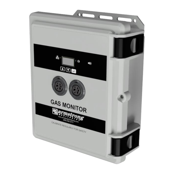
AMC-1BZ Gas Monitor 2.3 EXTERNAL VIEW Figure 2-1: External View Enclosure and Lid Assembly, UV Stabilized Polycarbonate, 11.750" L x 9.980" W X 5.460" (300 x 250 x 140 mm). Enclosure: IPx5 rating. Digital Displays the gas detection state (NORM for Normal, WARN for Warning, ALARM for High Alarm) -
Page 11: Figure 2-2: Internal View (Amc-1Bz2 Shown)
Figure 2-2: Internal View (AMC-1BZ2 Shown) Analog Input 1: Terminal Block for Zone 1 Input Analog Input 2: Terminal Block for Zone 2 Input (AMC-1BZ2 Only) Analog Output 1: Terminal Block for signal output 1 Analog Output 2: Terminal Block for signal output 2 (AMC-1BZ2 Only) -
Page 12: Accessories
Information processing and communications hub 12. Bus Power Module: Provides power and communications interface to the 1BZx 2.4 ACCESSORIES The following accessories are available for use with the AMC-1BZ Gas Monitors. See section 3.2.5 for RAM3 details. Accessory Description Order Code... -
Page 13: Installation
AMC-1BZ Gas Monitor 3 INSTALLATION The installation of the AMC-1B Gas Monitor is very important as the operational quality is a direct result of the quality of the installation. The following sections provide guidelines for installation, location and mounting, wiring, and cable selection. -
Page 14: Figure 3-1: Enclosure Mounting
AMC-1BZ Gas Monitor Figure 3-1: Enclosure Mounting ____________________________________________________________________________________... -
Page 15: Wiring
3.2.2 RELAYS The Monitor houses 2 relays for AMC-1BZ1 and 4 relays for AMC-1BZ2. The relay contacts are rated for 10Amps @ 28VDC/120VAC resistive. For relay contact arrangement, see Below. Note that default configuration is for the relays to be energized. -
Page 16: Analog In (Amc-122X Sensor Modules)
The AMC-RAM3 (Figure 3-3) provides a remote alarm indication when employed with monitors such as the AMC Gas Monitor 1B. Each RAM3 has a red strobe light to provide a visual indicator of an alarm condition and remains active until the alarm is cleared. The Audio alert is provided by a buzzer which emits a 2900hz tone at more than 90 dB(A) at 24 inches. -
Page 17: Operation
This section details the LED states and their corresponding meanings, as well as detailing the menu system available on AMC-1B monitors. Menu flow diagrams are available in section 7 as a quick reference to those already familiar with the menu system usage. -
Page 18: Table 4-1: Status Leds
AMC-1BZ Gas Monitor Table 4-1: Status LEDs LED States Network Alarm Status Sensor Module Display Screen Message Start Up • Initialization and Solid White AMC Splash Screen discovery of Sensor Modules (after UTx is powered up) • Sensor Warm-up Flashing Green... -
Page 19: Menu Overview
AMC-1BZ Gas Monitor 4.2 MENU OVERVIEW Note that a Menu Flow Chart is available in section 7. The menu images and menu flow diagrams in this manual represent gas types with labels such as “GAS1”, “GAS2”, etc. These are mapped to specific gases based on the customer order. -
Page 20: Menu System - Warning/Alarm Indication
AMC-1BZ Gas Monitor If the failure condition is resolved, the main display for the failed sensor will resume normal operation by indicating the sensor reading via a bar graph. 4.2.3 MENU SYSTEM – WARNING/ALARM INDICATION When a warning or an alarm occurs, the bar graph is replaced with a large WARN indication for warnings or a large ALARM for alarms. -
Page 21: Menu System - Fault Indication
AMC-1BZ Gas Monitor For units configured at factory to use latched alarms, when the alarm condition is cleared the display will indicate that the relays are latched until cleared by the user by pressing the ENTER button to release the latching condition. -
Page 22: Menu System - Detailed Sensor Screen
AMC-1BZ Gas Monitor 4.2.5 MENU SYSTEM – DETAILED SENSOR SCREEN To access more detailed information for each sensor, press and hold the button until the following screen appears The detailed sensor screen provides several values for each sensor. Use the DOWN buttons to page through all the attached sensors (1BCO will show only a single sensor). -
Page 23: Menu System - Detailed Status Screen
AMC-1BZ Gas Monitor 4.2.6 MENU SYSTEM – DETAILED STATUS SCREEN To access the detailed status for each sensor, press and hold the DOWN button until the following screen appears. The detailed status screen provides the complete status for each sensor. Use the DOWN buttons to page through all the attached sensors. -
Page 24: Menu System - Main Service Menu
AMC-1BZ Gas Monitor 4.2.8 MENU SYSTEM – MAIN SERVICE MENU 4.2.8.1 SERVICE MENU TIMEOUT The service menus remain unlocked for a programmed timeout period (set to 5 minutes). Within that period, the service menus can be re-enabled by long-pressing the ENTER button. -
Page 25: Menu System - External Sensor Service Menu
AMC-1BZ Gas Monitor With ‘Exit’ highlighted (as above), press ENTER to exit the service mode and return back to the main info screen as shown below. 4.2.9 MENU SYSTEM – EXTERNAL SENSOR SERVICE MENU NOTE: The Outputs menu (available from the main service menu) is used to provide supplemental configuration options that are applicable to external sensors, beyond those in the External Sensor Service menu. -
Page 26: Table 4-4: Analog Sub-Menu Options
AMC-1BZ Gas Monitor DOWN buttons can be used to navigate the list of analog configuration options for the selected external sensor. The analog configuration sub-menu is defined in Table 4-4: Table 4-4: Analog Sub-Menu Options Menu Item Description Fault (V) -
Page 27: Sensor Sub-Menu
AMC-1BZ Gas Monitor When the ENTER button is pressed with the last digit selected, the screen will update to display the confirmation dialog (described previously). If Yes is selected, the edit value is persisted as the new value for the current fault threshold for the selected external sensor. Otherwise, the edit value is rejected. -
Page 28: Gas Label
AMC-1BZ Gas Monitor 4.2.9.4 GAS LABEL If ‘Gas Label’ is activated from the ‘Sensor’ sub-menu, then the display will be updated to show the following editing screen. Each character can be edited to any alpha-numeric value (A-Z, 0-9) including a space. When... -
Page 29: External Sensor Custom Window Average
AMC-1BZ Gas Monitor When the ENTER button is pressed, the screen will update to display the confirmation dialog (described previously). 4.2.9.6 EXTERNAL SENSOR CUSTOM WINDOW AVERAGE Window is a custom average filter for gas readings, where the averaging "window" can be selected from a multiplier of 2-60. -
Page 30: Sim Enable
AMC-1BZ Gas Monitor 4.2.9.9 SIM ENABLE If ‘Sim Enable’ is activated from the ‘Override’ sub-menu, then the display will be updated to show the following editing screen. When the ENTER button is pressed, the confirmation screen (described previously) is displayed. -
Page 31: Menu System - Transmitter Service Menu
AMC-1BZ Gas Monitor 4.2.10 MENU SYSTEM – TRANSMITTER SERVICE MENU If the ‘UTx’ menu item is activated from the main service menu via the ENTER button, then UTx service menu will appear on the display as shown in the following diagram. -
Page 32: Transmitter Sensors Settings
AMC-1BZ Gas Monitor 4.2.10.1 TRANSMITTER SENSORS SETTINGS From the UTx service menu, selecting ‘Sensors’ will update the display to show the following sub- menu. DOWN buttons can be used to navigate the list of configured sensors for the sensors sub-menu. - Page 33 AMC-1BZ Gas Monitor Zero Buff Select this menu item to edit the zero buffer level for the display of small gas concentrations. Cal Freq Select this menu item to edit the time period between re-calibrations Exit Select this menu item to return to the Sensors sub-menu 4.2.10.2.1 SETPOINT...
-
Page 34: Table 4-11: Calibration Frequency Configuration
AMC-1BZ Gas Monitor When the ENTER button is pressed, the screen will update to display the confirmation dialog (described previously). If Yes is selected, the edit value is persisted as the new value for the Zero Buffer for the selected sensor. Otherwise, the edit value is rejected. In either case, the menu returns to the Sensor sub-menu menu with the ‘Zero Buff’... -
Page 35: Transmitter Alarms Settings
AMC-1BZ Gas Monitor 4.2.10.3 TRANSMITTER ALARMS SETTINGS From the UTx service menu, selecting ‘Alarms’ will update the display to show the following sub- menu. DOWN buttons can be used to navigate the list of menus for the Alarms sub-menu. Table 4-12... -
Page 36: Table 4-13: Transmitter Alarm Sub-Menu Settings
AMC-1BZ Gas Monitor Table 4-13: Transmitter Alarm Sub-Menu Settings Menu Item Description Select this menu item to edit the alarm’s enable state Enable Select this menu item to edit the alarm’s source (i.e. from the available sensors) Source Select this menu item to edit the alarm’s input value Input Select this menu item to edit the alarm’s setpoint... -
Page 37: Table 4-14: Alarm Input Options
AMC-1BZ Gas Monitor When the ENTER button is pressed, the screen will update to display the confirmation dialog (described previously). 4.2.10.4.3 INPUT If ‘Input’ is activated from the alarm sub-menu, then the display will be updated to show the following editing screen. -
Page 38: Table 4-15: Alarm Setpoint Options
AMC-1BZ Gas Monitor The available options for ‘Level’ are listed in Table 4-15. Table 4-15: Alarm Setpoint Options Menu Item Description Alarm SP 1 Alarm setpoint 1 from the selected source Alarm SP 2 Alarm setpoint 2 from the selected source... - Page 39 Otherwise, the relay will not activate. NOTE: Relays 3 through 5 are unavailable in the AMC-1B Series. Any attempt to toggle the state of a checkbox associated with an unavailable relay will be ignored.
- Page 40 AMC-1BZ Gas Monitor When the ENTER button is pressed while the last digit is highlighted, the screen will update to display the confirmation dialog (described previously). ____________________________________________________________________________________...
-
Page 41: Transmitter Relay Settings
AMC-1BZ Gas Monitor 4.2.10.5 TRANSMITTER RELAY SETTINGS From the UTx service menu, selecting ‘Relays’ will update the display to show the following sub- menu. DOWN buttons can be used to navigate the list of menus for the Alarms sub-menu. Table 4-17... -
Page 42: Table 4-19: Relay Polarity Menu
AMC-1BZ Gas Monitor If ‘Polarity’ is activated from the relay sub-menu, then the display will be updated to show the following editing screen. The available options for ‘Polarity’ are listed in Table 4-19. Table 4-19: Relay Polarity Menu Menu Item... -
Page 43: Outputs
AMC-1BZ Gas Monitor 4.2.10.6 OUTPUTS Analog output configuration is handled via the Outputs menu available from the main service menu. With the Outputs menu it is possible to configure the analog output to use multiplexed sensor sources to determine the output response; this section concludes with an example. Once... - Page 44 AMC-1BZ Gas Monitor To the right of each enabled gas an “M” or “A” in brackets denotes which gas concentration is The “M” indicates that the maximum supported gas used in scaling the output response. concentration of the sensor is used in scaling the output response. An “A” indicates that the gas concentration tied to the high alarm (Alarm SP 3, see section 4.2.10.1 is used as max scale in the...
- Page 45 AMC-1BZ Gas Monitor 4.2.10.6.3 RANGE From the Outputs menu, when the ENTER button is pressed with Range selected, a sub-menu to configure the minimum and maximum analog output response will become available. The engineering unit (V or mA) displayed in the Output Min/Max menu items will reflect the analog output mode selected with the Mode menu item.
-
Page 46: Buzzer
AMC-1BZ Gas Monitor 4.2.10.6.4 MULTIPLEXING EXAMPLE With an overview of the Outputs menu complete, it is worthwhile to show an example of how a multiplexed sensor configuration can be used to drive the analog output. In this example, the following configuration is used: •... -
Page 47: Activation Timer
AMC-1BZ Gas Monitor The available options for ‘Buzzer’ are listed in the following table. Table 4-21: Buzzer Menu Menu Item Description None Disable local buzzer completely Alarm Local buzzer sounds for alarm level and fault All Levels Local buzzer sounds for warning, alarm, high alarm levels, and fault 4.2.10.8 ACTIVATION TIMER... -
Page 48: Rtc Date & Time
5.1 GENERAL The AMC-1B should be cleaned (brushed or wiped) as required, depending on the rate of accumulation of any dust or dirt. To avoid damage, the unit MUST NOT be submerged, hosed or splashed with any liquids. -
Page 49: Led/Relay Activation Test
AMC-1BZ Gas Monitor 5.2.1 LED/RELAY ACTIVATION TEST The Main Service Menu allows the activation of all relays and LEDs, regardless of alarm state. This may be useful during system configuration to verify operation of the LEDs and relays, as well as to verify that the polarity settings are correct. -
Page 50: Troubleshooting
AMC-1BZ Gas Monitor 6 TROUBLESHOOTING Table 6-1 Troubleshooting Table Symptom Possible How to Verify Corrective Action Cause Buzzer or Bad Connection No continuity between COM Re-seat wiring connections for Relays not to Buzzer or and NO Bus Module buzzer and relay coils. -
Page 51: Menu Flow Diagrams
AMC-1BZ Gas Monitor 7 MENU FLOW DIAGRAMS Figure 7-1: Main Screen / Password Flow ____________________________________________________________________________________... -
Page 52: Figure 7-2: Service Menu Flow Diagram (A)
AMC-1BZ Gas Monitor Figure 7-2: Service Menu Flow Diagram (a) ____________________________________________________________________________________... -
Page 53: Figure 7-3: Service Menu Flow Diagram (B)
AMC-1BZ Gas Monitor Figure 7-3: Service Menu Flow Diagram (b) ____________________________________________________________________________________... -
Page 54: Figure 7-4: Sensor Configuration Menu Flow Diagram
AMC-1BZ Gas Monitor Figure 7-4: Sensor Configuration Menu Flow Diagram ____________________________________________________________________________________... -
Page 55: Figure 7-5: Alarm Menu Flow Diagram
AMC-1BZ Gas Monitor Figure 7-5: Alarm Menu Flow Diagram ____________________________________________________________________________________... -
Page 56: Figure 7-6: Outputs Menu Flow Diagram
AMC-1BZ Gas Monitor Figure 7-6: Outputs Menu Flow Diagram ____________________________________________________________________________________... -
Page 57: Revision History
AMC-1BZ Gas Monitor 8 REVISION HISTORY Table 8-1: Document Revision History Revision Release Date Change Description January 2024 Initial Release ____________________________________________________________________________________...
Need help?
Do you have a question about the AMC-1BZX and is the answer not in the manual?
Questions and answers