Advertisement
SERVICE MANUAL
TECHNICAL INFORMATION
I FOR SERVICE PERSONNEL ONLY I
SPECIFICATIONS
SPECIFICATIONS AND PARTS ARE SUBJECT TO CHANGE FOR IMPROVEMENT
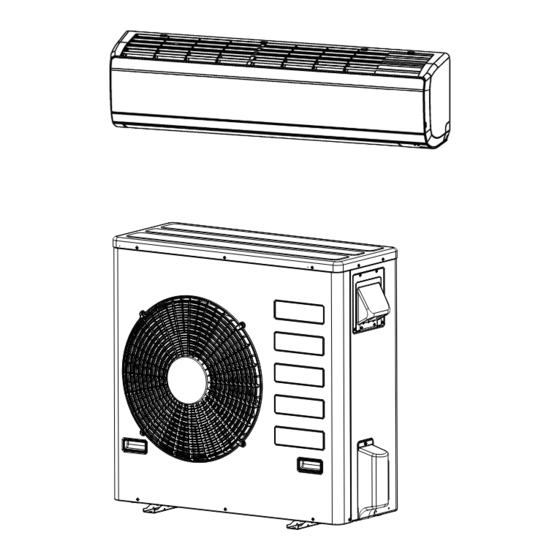
ROOM AIR CONDITIONER
RAS-EH36PHLAE
RAC-EH36WHLAE
INDOOR UNIT + OUTDOOR UNIT
1
I
I
NO.0753E
PM
RAS-EH36PHLAE
RAC-EH36WHLAE
REFER TO THE FOUNDATION MANUAL
CONTENTS
SPECIFICATIONS ----------------------------------------------------------------- 6
HOW TO USE ---------------------------------------------------------------------- 9
CONSTRUCTION AND DIMENSIONAL DIAGRAM --------------------- 38
MAIN PARTS COMPONENT -------------------------------------------------- 40
WIRING DIAGRAM --------------------------------------------------------------- 42
CIRCUIT DIAGRAM --------------------------------------------------------------- 44
PRINTED WIRING BOARD LOCATION DIAGRAM --------------------- 47
BLOCK DIAGRAM ---------------------------------------------------------------- 53
BASIC MODE -------------------------------------------------------------------- -- 54
REFRIGERATING CYCLE DIAGRAM -------------------------------------- 64
AUTO SWING FUNCTION ------------------------------------------------------ 65
DESCRIPTION OF MAIN CIRCUIT OPERATION ----------------------- 66
DISASSEMBLE & ASSEMBLY PROCEDURE --------------------------- 10 1
TROUBLE SHOOTING ---------------------------------------------------------- 110
PARTS LIST AND DIAGRAM -------------------------------------------------- 134
� After installation
MAY 2021
Advertisement
Table of Contents

Related Manuals for Hitachi RAS-EH36PHLAE


Summary of Contents for Hitachi RAS-EH36PHLAE
-
Page 1: Table Of Contents
NO.0753E RAS-EH36PHLAE RAC-EH36WHLAE SERVICE MANUAL TECHNICAL INFORMATION REFER TO THE FOUNDATION MANUAL I FOR SERVICE PERSONNEL ONLY I CONTENTS SPECIFICATIONS ----------------------------------------------------------------- 6 HOW TO USE ---------------------------------------------------------------------- 9 RAS-EH36PHLAE CONSTRUCTION AND DIMENSIONAL DIAGRAM --------------------- 38 MAIN PARTS COMPONENT -------------------------------------------------- 40 WIRING DIAGRAM --------------------------------------------------------------- 42... - Page 2 (R410A)
- Page 5 -18℃(-0.4 °F). -18℃(-0.4 °F)
- Page 6 RAC-EH36WHLAE MODEL RAS-EH36PHLAE MOTOR 120W FAN MOTOR CAPACITOR FAN MOTOR PROTECTOR ATL253UDPC9AQ COMPRESSOR COMPRESSOR MOTOR OVERLOAD PROTECTOR PROTECTOR 5.0A FUSE (for MICROPROCESSOR) POWER RELAY POWER SWITCH TEMPORARY SWITCH SERVICE SWITCH TRANSFORMER ERZV9V431 NOISE SUPPRESSOR YES(IC) YES(IC) THERMOSTAT REMOTE CONTROL SWITCH...
- Page 7 INDOOR MODEL : RAS-EH36PHLAE...
- Page 8 OUTDOOR MODEL : RAC-EH36WHLAE 65-39/64ft(20m), 16-13/32ft(5m) above 27-9/16in(100mm) above 3-15/16in(100mm) above 3-15/16in (100mm) 5/8in above 7-7/8in(200mm) above 27-9/16in(700mm)
- Page 9 Important Notice • Johnson Controls-Hitachi Air Conditioning North America LLC pursues a policy of continuing improvement in design and performance in its products. As such, Johnson Controls-Hitachi Air Conditioning North America LLC. reserves the right to make changes at any time without prior notice.
- Page 10 SAFETY PRECAUTION • Please read the "Safety Precaution" carefully before operating the unit to ensure correct usage of the unit. • To prevent personal injury or property damage, read this section carefully before you use this product, and be sure to comply with the following safety precautions.
- Page 11 PRECAUTIONS DURING OPERATION • The product shall be operated under the manufacturer specification and not for any other intended use. • Do not attempt to operate the unit with wet hands, this could cause fatal accident. • When operating the unit with burning equipments, regularly ventilate the &...
- Page 12 Please refer to the Remote Manual provided for functions and operation details. OUTDOOR UNIT Drain port MODEL NAME AND DIMENSIONS MODEL NAME AND DIMENSIONS WIDTH in(mm) HEIGHT in(mm) DEPTH in(mm) MODEL RAS-EH36PHLAE 43.31”(1100) 11.81” (300) 10.24” (260) RAC-EH36WHLAE 37.40”(950) 37.20” (945) 14.57” (370)
- Page 13 INDOOR UNIT INDICATORS OPERATION LED This LED lights during operation. The OPERATION LED fl ashes/dimming in the following cases during heating. (1) 1) During preheating For about 2–3 minutes after starting up. (2) 2) During defrosting Defrosting is performed about once every one hour when frost forms on the heat exchanger of the outdoor unit, for 5–10 minutes each time.
- Page 14 THE IDEAL WAYS OF OPERATION Suitable Room Temperature Install curtain or blinds Warning It is possible to reduce heat Freezing temperature entering the is bad for health and a room through waste of electric power. windows. Ventilation Effective Usage Of Timer At night, please use the "OFF or ON timer Caution or SLEEP timer operation mode", together...
- Page 15 FOR USER'S INFORMATION The Air Conditioner And The Heat Source In The Room Caution If the amount of heat in the room is above the cooling capability of the air conditioner (for example: more people entering the room, using heating equipments and etc.), the preset room temperature cannot be achieved.
- Page 16 ATTACHING THE AIR PURIFYING FILTERS Open the front panel Pull up the front panel by holding it at both ● sides with both hands. Remove the Pre- fi lter Push upward to release the clasps and pull ● out the Pre-fi lter. Attaching the air purifying fi...
- Page 17 MAINTENANCE CAUTION Cleaning and maintenance must be carried out only by qualified service personnel. Before cleaning, stop operation and switch off the power supply. PRE-FILTER Clean the Pre-filter, as it removes dust inside the room. In case the Pre-filter is full of dust, the air flow will decrease and the cooling capacity will be reduced.
- Page 18 CLEANING OF FRONT PANEL • Remove the front panel and wash with clean water. Wash it with a soft sponge. After using neutral detergent, wash thoroughly with clean water. • When front panel is not removed, wipe it with a soft dry cloth.
- Page 19 • CAUTION • Please use ground wiring. Do not place the ground wiring near water or gas pipes, lightning-conductor, or the ground wiring of telephone. Improper installation of ground wiring may cause electric shock. • A circuit breaker should be installed depending on the mounting site of the unit. Without a circuit breaker, the danger of electric shock exists.
- Page 20 AFTER SALE SERVICE AND WARRANTY WHEN ASKING FOR SERVICE, CHECK THE FOLLOWING POINTS. CONDITION CHECK THE FOLLOWING POINTS If the remote controller is • Do the batteries need replacement? not transmitting a signal. • Is the polarity of the inserted batteries correct? Remote controller display is dim or blank.) •...
- Page 21 Please note: On switching on the equipment, particularly when the room light is dimmed, a slight brightness fluctuation may occur. This is of no consequence. The conditions of the local Power Supply C ompanies are to be observed . Note •...
- Page 22 PREPARATION BEFORE OPERATION When using the remote controller, if there is no response from the air conditioning unit and/or the display has faded and dimmed, the batteries in the remote control need to be removed and replaced with a new set. Push and pull to the direction of arrow ■...
- Page 24 Temperature Switching The default temperature display for this model is Fahrenheit ( F) . ° To switch the temperature display from Celsius to Fahrenheit T .:'.; Press and hold button for 3s . Release Reset button while pressing I T .:'.; I until Reset LCD shows Full Segment display.
- Page 25 Multi Ty pe outdoor unit. Press the MODE selector button to select and display (AUTO) mode. ® HITACHI ,.,,., • When AUTO mode is selected, the room air conditioner automatically selects either HEAT or COOL mode depending on the current room temperature.
- Page 26 To maintain the reliability of the room air conditioner, please operate when outdoor temperature is above ■ minimum operating range. Press the MODE selector button to select and display � (HEAT) mode. HITACHI Set the desired FAN SPEED using (FAN SPEED) button. The display indicates the setting. ;i:J °...
- Page 27 If indoors humidity is very high (80%), some dew may form on the air outlet grille of the indoor unit. Press the MODE selector button to select and display ¢ (COOL) mode. HITACHI ,. , . - f Set the desired FAN SPEED using Fan,eed (FAN SPEED) button.
- Page 28 ° ° Press the MODE selector button to select and display (DEHUMIDIFY) mode. HITACHI The fan speed is set at LOW..JO•F Set the desired FAN S P EED with the Fan , eed ( FA N S PEE D) butt o n .
- Page 29 FAN OPERATION Use the unit as an air circulator. Press the M ODE selector button so that the display indicates (FAN ) . HITACHI • r � Press the Fan Speed (FAN SPEED ) button. {HIGH ) ---►� ( M ED ) �...
- Page 30 (POWERFUL) button during HEATING, DEHUMIDIFYING, COOLING, FAN or AUTOMATIC operation, the air conditioner operates at maximum power. ■ During POWERFUL operation, cooler or warmer air flow will be blown out from the indoor unit for COOLING or HEATING operation respectively. HITACHI ,.,.-. I � I �...
- Page 31 ~ 60 F (10 ~ 16 ° ° ° ° ° ° HITACHI Leave Home Press the (LEAVE HOME) button to activate the ,i:j, function. Room temperature is set at 50 F (10 C) and HEATI N G operation �!..l °...
- Page 32 CLEAN {ONE TOUCH CLEAN) OPERATION (For Multi-model connection) Use this function to dry the heat exchanger of the indoor unit to prevent formation of mildew. HITACHI F.W/CL • Press the � (FROST WASH/CLEAN) button when unit is in Standby mode.
- Page 33 � I F.W/CL When the unit is off, press (FROST WASH/CLEAN) button, manual Frost Wash will start. ■ How to start and cancel Frost Wash (Manual mode) HITACHI I � I F.W/CL " • Press (FROST WASH/CLEAN) button, " [ is displayed �[j...
- Page 34 ECO operation is an energy saving function by changing set temperature automatically and limiting the maximum power consumption value. By pressing the (ECO) button during HEATING, HITACHI -,. - . AUTO, DEHUMIDIFYING or COOLING operation, the unit performs ECO operation .
- Page 35 Silent I � I • When button is pressed, HITACHI ,.,,.. • " b&J "will be displayed on the LCD. • Fan speed will be in silent c:-_;) . �...
- Page 36 Mode Indication hour-+ 2 hours-+ 3 hours -+ 7 hours Sleep timer HITACHI Sleep timer off ,. " f � � During Sleep Timer, the unit will continue working for the ¢...
- Page 37 ADJUSTING THE AIRFLOW DIRECTION Ad just the airflow upward and downward HITACHI The horizontal air deflector is automatically set to the specific angle that is suitable for each operation. The deflector can swing up and down and set to UP/Down ,.,,.f...
- Page 38 MODEL RAS-EH36PHLAE Unit: Inch (mm) '43.30"(1100) 10.24"(260) \•/ ......1.85"(47) 1.85"(47) 2.36"(60) 2.36"(60) 3.66"(93) 21.65"(550)
- Page 39 MODEL : RAC-EH36WHLAE Unit: Inch (mm) 37-13/32 (950) 3-3/16 (81) 1-37/64 (40) 14-9/16 (370) 1-19/64 (33) Service valve Φ6.35) 1/4( Service valve Φ15.88) 5/8( Air suction grille Air outlet 9-9/16 (243) Holes for anchor bolt (2-Ø12.5) 1-57/64 (48) 3-15/16(100) (200) Notch for anchor bolt 23-5/8 (600) 6-57/64 (175)
-
Page 40: Specifications
MAIN PARTS COMPONENT THERMOSTAT (Room Temperature Thermistor) Thermostat Specifications RAS-EH36PHLAE MODEL MODEL MODE COOL HEAT 20.0 (68.0) 15.6 (60.1) 15.3 (59.5) 20.7 (69.3) ℃( °F) 28.0 (82.4) 23.6 (74.5) 28.7 (83.7) 23.3 (73.9) 36.0 (96.8) 31.6 (88.9) INDICATION 36.7(98.1) 31.3 (88.3) - Page 41 COMPRESSOR MOTOR Comrpessor Motor Specifications RAC-EH36WHLAE MODEL ATD253UDPC9AQ COMPRESSOR MODEL PHASE SINGLE RATED VOLTAGE RATED AC 220~240V FREQUENCY POLE 50Hz NUMBER CONNECTION YELLOW ° 0.932 ° RESISTANCE VALUE (Q) IACAUTION When the Air Conditioner has been o p erated for a lon g time with the ca p illar y tubes clo gg ed or crushed or with too little refri g erant , check the color of the refri g erant oil inside the com p ressor.
-
Page 42: Wiring Diagram
WIRING DIAGRAM MODEL RAS-EH36PHLAE INDOOR UNIT BLUE YELLOW BROWN WHITE GRAY ORANGE GREEN BLACK PINK VIOLET IVORY... - Page 43 MODEL RAC-EH36WHLAE OUTDOOR UNIT...
-
Page 44: Circuit Diagram
CIRCUIT DIAGRAM Remote Controller � ----=-=- ��������� ��� :::�O\OOr-..\01.t")'q"MN.- V'IV'IV'IV'IV'IV'IV'IV'IV'IV'IV'I � LCD1 HT69F VMN.-00\00r--.\OL.f".IVM NNNNN.-.-.- " SEG12 COMO � " SEG11 COM1 SEG10 , i;J]ttf 1 SEGO COM2 PE2/SEG10 PF7/SEG23 " SEG9 R1,R2, R3,R4 7'J,fJ1.�jil;� '\. t)J:@'2 COM3 / COM3 PE1/SEG9 COM3/SEG24 �... - Page 45 CAPACITOR DIODE VALUE ASSY. VALUE ASSY SYMBOL TOLERANCE WATT FORM GROUP REMARK SYMBOL TOLERANCE WATT FORM GROUP REMARK (˜) (˜) MODEL RAS-EH36PHLAE FORM GROUP ASSY R001 VALUE ASSY SYMBOL MODEL R651 1/16 A , B 1005 SYMBOL VOLTAGE TYPE FORM GROUP REMARK µ...
- Page 46 CIRCUIT DIAGRAM MODEL: RAC-EH36WHLAE MAIN PWB,HIC PWB...
-
Page 47: Printed Wiring Board Location Diagram
PRINTED BOARD LOCATION DIAGRAM MODEL: RAS-EH36PHLAE MAIN P.W.B Marking on P.W.B RECEIVING P.W.B SENSOR P.W.8 Marking on P.W.B Marking on P.W.B ..:!L la Cl!l'5l IMI... - Page 48 RAC-EH36PWHLAE...
- Page 49 RAC-EH36PWHLAE...
- Page 50 RAC-EH36PWHLAE...
- Page 51 RAC-EH36PWHLAE...
- Page 52 RAC-EH36PWHLAE...
- Page 53 Indoor / Outdoor interface circuit DC fan motor Indoor DC fan motor drive circuit Control Power circuit Operation Reset circuit Indicating lamp Timer ECO Sensor Buzzer circuit Wireless receive Wireless remote /send circuit controller Room temperature thermistor Vertical sweep motor 1 (20L6M0) Heat exchanger thermistor...
-
Page 54: Basic Mode
□ ■ ■ ■ ■ ■ □ ■ BASIC MODE Cooling Dehumidifying Heating Auto Basic operation of start/stop button Start Stop Start Stop ■ s : r11stop button 0 eration lamp - - - - - - - Startlsto button • Reserve button ancel hutton Ooeration lam... - Page 55 Basic Cooling Operation Room temperature Fan s eed set to "auto" Stop Start StarVstop switch Thermo judgment Thermo OFF Silent Ultra-Lo Operation lamp 1min. Max. Rating 3000 Min. Outdoor fan Reversing valve (heating "on" mode) Notes: (1) Condition for entering into Cool Dashed mode. When fan set to "Hi" or "Auto and when the compressor speed (P section) due to temperature difference between setting temperature (including the correction shift only) and room temperature is CMAX or higher.
- Page 56 Cooling Powerful Operation Cooling Defrost "POWERFUL" setting Cool i t i o Temperature setting �M; �dw ; �=S = -=- :. -=-;.-=-;.-=-;.-=-;.-=-;.-=-;.-=-;.-=-;.-=-; t';:':_� _ = s _ = · ��;:_-:=_-:=_ -:=_-:=_-:=_-:=__-=. : -=- : -=- : -=- : ·:::_-;: t-- ---- � --+----- -=-: -=-: �:...
- Page 57 Dehumidifying 30sec. Room temperature ·ud ement Room temperature C") Cooling preset temperaure 1---+--+---+---�---------------------- --.-: ,,..- ====- --------+-------jl------------ ----, .L--+------- () () (<:! c.o Start Start/Stop Switch Operation lamp Thermostat judgement Indoor fan Lo/Silent 15 sec. 1 sec. I- L � t�CJiiiiiiiliiiiii■ii�======��=============================1■iiiiiiiiii■ii�====�====·••iiiiiiiE�===�==·••iiiiiiiiiiliii■il�::: Outdoor fan Reversing valve 1 min.
- Page 58 Dehumidifying Powerful Operation "POWERFUL" setting Temperature setting PWSFTSD "'C SDMAX Notes: (1) Pressing the "POWERFUL" button will reduce the temperature setting by PWSFTSD. (2) The powerful operation is for 20 minutes after setting. (3) Operation is continued forcibly thermo-ON for 20 minutes after the powerful operation is finished. (4) Pressing the "START/STOP"...
- Page 59 Basic Heating Operation Healing set temperature (remote control set temperature (+)) 1e·c Fan speed set to "auto" Stop Start Stop Start Stop Start/stop button Thermo OFF Thermo judgment Defrost signal 30sec. _::�:j±C::::::::::_---Jl•�- --------+-_:_:: =• • = . tjjjo:Jll����-�:____j_------+----WfJl�L-----l-------c-=-----=� :f:JIE�-----W Indoor fan � ----c-=- 15sec.
- Page 60 Setting Defrosting Inhibit Period Reversing valve defrosting 15' or more Auto fresh defrosting Over efrosting inhibit perio Fan spee Stop DFTIM_OT P5 Start/Stop button set to "Hi" Defrost signal � DFTIM_OTP 10 Preheating released Preheating released Preheating ju gment Preheatin --------�--�---�-- -L---_j•-----�------L-J__LJl_ ___ L __________ DFTIM_OT PO...
- Page 61 Heating Powerful Operation Leave Home Le ave Home settemperaturebo it:: � � �o�. s i s ·�cI:=:=:=:=:=:=��=!1==:=::=:!������======E:='::�= (10'C+SFTLVHM) "POWERFUL" setting 1----------1 Thermo OFF Start Stop PWSFTW Temperature setting I-------+-_,_ StarVStop swi c h I n i t i al FUDI L VH1,2 "C Horizontal air deflrector Operation lamp...
- Page 62 ECO button ° ° Cooling:1.00 C Dehumidifying:1.00 Set temperature Current restrict Compressor speed Notes: • Can't set POWERFUL and ECO at the same time. • During FAN operation,can't set ECO.
- Page 63 Clean Operation CLEAN operation period 60' CLEAN button Operation mode Operation lamp Indoor fan Outdoor fan Compressor speed Notes: (1) During CLEAN operation period, heating mode will change to fan mode when HEX temparature is "CLNEVP" or more except force 3 minutes operation. (2) For multi connections, CLEAN operation is limited to fan mode.
- Page 64 RAS-EH36PHLAE / RAC-EH 36WHLAE THERMISTOR 2S-VALVE Ø6.35mm (1/4") 5S-VALVE Ø15.88mm(5/8") THERMISTOR 2S-VALVE Ø6.35mm (1/4") 5S-VALVE Ø15.88mm(5/8")
- Page 66 MODEL: RAS-EH36PHLAE . Control power circuit LOOI � 8.5V FUI 3.15A fuse § § S',! § Switching power circuit Fig. 1 -1 • An AC power supply from indoor unit passes through the 3. 1 5A fuse, varistor (VA001 ), and noise filter circuit and rectified and smoothed by DB1 and C003 to become a DC current 3 25 V.
- Page 67 2. Reset Circuit Microcomputer (612 Fig. 3-1 Timing chart Voltage ------------1 � - s _ . o_ v _�� @ pin of IC501 supply voltage RES canceling voltage 4.4V Voltage " __.l - -+----------..; pin of IC501 output voltage �-s . _ o v _ or @ pin of microcomputer Fig.
- Page 68 3. Drive circuit ofthe indoor fan motor Primary 18.SV � --- R201 "' '" � Primary0V -----------------+-!--_____ ____,.., Rotation speed feedback signal (to pin © of microcomputer) -!-- -- ..- - Output signal of indoor fan (to pin @of microcomputer) ----'\"t'v---+----+� R213 Fig.
- Page 69 4. Buzzer Circuit Microcomputer Buzzer output Fig.4 - 1 Buzzer Circuit • When the buzzer sounds, an approx. 3.9kHz square sigl).8.l is output from buzzer output pin ®of the micro computer. After the amplitude of this signal has b een set to 12Vp- P by a Piezoelectric element Metal diaphragm transistor, it is applied to the buzzer.
- Page 70 6. Room temperature, heat exchanger thermistor circuits Microcomputer lnidcation P.W.B MAIN P.W.B CN16A CN16 Heat exchanger thermistor input Room temperature 90 , ___ -+---w..,__.o----+-f--1 thermistor input • The thermistor is used for detecting the room temperature and indoor unit heat exchanger pipe temperature. •...
- Page 71 8. Initial Setting Circuit (1(531) • When power is supplied, the microcomputer reads the data in 1(531 (E PROM) and sets the preheating activation value and the rating and maximum speed of the compressor, etc. to their initial values. • Data of self-diagnosis mode is stored in 1(531; data will not be erased even when power is turned off. Microcomputer Fig.
- Page 72 "' t-+--+---++-+--+--+---<-+--+---t 0 f-<f+----l--+!+-+-,o+.1f-+----,t-+---+<l-l :':, f-<ttttltt>---fftlt-ttttlflfff--+-IIIH--ttt ;'.; 1-+++--+---++-t--<l+-l'-+--+-+-+-++---l OY �IIIII-III--IIIII-IIIIIIIIN---1--11111--111- 10. Indoor/outdoor communication circuits Indoor unit side Outdoor unit side Inverter circuit Outdoor C302 T microcomputer 'jlOV Indoor transmission circuit Indoor microcomputer {IC601} Outdoor reception input Indoor transmission output Indoor reception input Indoor unit reception circuit Fig.10-1 T he unit is receiving a signal that it sent...
- Page 73 Check I If a cable poorly inserted in the indoor terminal board or some other failure overheats the terminal board and the temperature fuse of the terminal board blows out, the power to the indoor communication circuit will be shut down to stop the communications function.
- Page 74 11. Stepping motor drive circuit Microcomputer Vertical air flow L-�4 Vertical air flow L-�3 Vertical air flow L-�2 Vertical air flow L-�1 CN12 Horizontal air flow R-�4 Horizontal air flow R-�3 Horizontal air flow R-�2 Horizontal airflow R-�1 Fig. 11-1 [Connector circuit waveform while the motor runs] Voltage waveforms of different phases as viewed from the OV line while the motor rotor is turning counterclockwise...
- Page 75 12. Run status and alarm signal output circuit ICN51 848-XH-A Microcomputer R511 R800 OPERATION LAMP 2 9 OPERATION OUTPUT Fig.12-1 Fig.12-1 is the control circuit of run status and signal output in main PWB.The pin@ of CNS is used to show run status and the pin @ of CNS is used to warn people when failure occurrence. If customer want to use this function, need to use the adapter(sold separately) to achieve it.
- Page 76 MODEL: RAC-EH36WHLAE AC208-230V...
- Page 78 -230V...
- Page 79 -230V...
- Page 80 AC220-230V AC208-230V -230V...
- Page 83 Main Main...
-
Page 93: Service Call Q&A
SERVICE CALL Q&A Cooling operation The compressor sometimes Cooling when the room Check if the heat stops during cooling. temperature is low may exchanger of the indoor cause the heat exchanger unit is covered with frost. of the indoor unit to gather Wait for 3 to 4 minutes frost. - Page 94 Common, etc. In fan speed "automatic" mode, In "automatic fan speed" mode, the This does not abnormal. It the product will sense the heat indoor fan changes from strong fan speed is because the cold fan exchange temperature and, to weak fan speed to slight fan speed. speed prevention is working.
- Page 95 Wireless remote control The timer will not become set. Have you set the product to the current time? The timer cannot be set unless it is set to the current time. The current time When set to the current The current time display will disappears 10 seconds time setting, the reading disappear at once.
- Page 96 Procedure for Disassemble and Reassemble MODEL : RAS-EH36PHLAE 1. Front Panel 3. Main P.W.B and Reception/Indication P.W.B (1) Remove each connector from the lead wire. (1) Pull the panel by holding it both lower sides with both hands. (2) Remove the two P.W.B supports from the main P.W.B.
- Page 97 (4) Remove the two lock screws from the fan motor holder and one screw from the evaporator support plate. (5) Pull up the evaporator by holding it at the lower side. Insert a screwdriver through the space between the evaporator and fan motor holder and loosen the fan lock screws to remove the air fow fan and fan motor.
- Page 98 CN12 CN18 CN16A CN12 CN17 CN16A...
- Page 99 Other instructions (1) Detaching and reattaching the receptacles for tab terminal All the receptacles for connecting tab terminals are with a locking mechanism. Forcibly pulling any such receptacle without unlocking it will destroy it. Be on guard. When reconnecting it, insert it securely all the way home. ・Receptacle types and how to unlock them Mild resin cover Cancel button...
-
Page 100: Trouble Shooting
Troubleshooting support Function Self-diagnosis display ・The failure mode detected on the indoor unit side is displayed by [Display on the indoor blinking the "timer lamp". And a failure detected on the outdoor unit side] unit side will be indicated by the "time lamp" blinking 4 times. ・If the outdoor unit side detects a failure, the product will first conduct several operation retrials. - Page 101 MODEL RAC-EH36WHLAE...
- Page 102 (2 places). (2 places)
- Page 107 5/8” (15.88mm) (5/8)
- Page 108 BLOWING/DISCONNECTION OF FU1(3.15A) SELF-DIAGNOSIS DISPLAY MODE (INDOOR SIDE) MODEL RAS-EH36PHLAE While the "timer lamp" (orange), of the indoor unit is blinking, troubleshoot the product while referring to the table below. 1. How to count the lamp blinking frequency [An example of 5-time blinking] ·The product will repeat blinking with 2-second...
- Page 109 [Lighting modeoftheseI f -diagnosis I a mp Lighting mode of the self-diagnosis lamp L E D INDICATI O N DURING COMPRESSOR OPERATE ADANGER&E|ectricshocknsk(DC360V) EE0023959A L D 301 I OPERATION STATUS 焉 三 二 昙髻昙焉霆启昙言 靡气:NOF[R RM AL) THAT IT IS BELOW 1 OV T廿EN ONLY CAN START T廿E SERVICING WORK. OORINGUNIT STOP,10归i|“IIE1H[Rl)1[COlPRESSOR ORl)1[El£CTR|(')j_|S F/IJLTY!!\IENSElf-D盼庥IS BUNK 1,3 , i OR 511 从...
- Page 110 SELF-DIAGNOSIS DISPLAY MODE (OUTOOR SIDE) MODEL RAC-EH36WHLAE AC208-230V...
- Page 111 Self Diagnosis Memory Function Failure mode are stored in the non-volatile memory of indoor unit and can be redisplay by operating the remote controller. This function is very useful in checking the failure modes when either unintentionally switching OFF power supply or restarting the unit operation without conforming the number of blinking of self diagnosis lamp.
- Page 112 1. While pressing and holding (ON/OFF) butt on and button, press [RESET ] button on the same. Release [RESE T] button only and make sure that all marks on the remote controller display are indicated then release the (ON/OFF) butt on and button.
- Page 113 SETTING THE PREVENTION OF MUTUAL INTERFERENCE FOR REMOTE CONTROLLER a.) Other indoor circuit breakers should be disconnected. b.) Remove the back cover of the remote control. c.) Cut the jumper as shown below. d.) Press “Reset” button after installing the battery. e.) Corresponding to the room electrical box dial code 6 to dial on.
- Page 114 HOW TO CHANGE THE FAN SPEED IN COOLING MODE DURING THERMO OFF The fan speed in Cooling Mode during thermo off can be changed by the remote controller. (This procedure shall be implemented strictly by service personnel only.) It is possible to return it to the default setting. PROCED U R E Press [POWERFUL] button and...
- Page 115 HOW TO CHANGE THE INTERMITTENT FAN HEATING SETTING The intermittent fan control during thermo o˜ in Heating mode can be changed by the remote controller. (The procedure should be done only by service personnel.) It is possible to select from 3 patterns. PROCEDURE Press (POWERFUL) button,...
- Page 116 DISPLAY OPERATION MODE SETTING For operating indoor unit independently (without outdoor unit connection), remote controller must be set according to below procedures before send the signal to the indoor unit. New communication format between indoor and outdoor is required to communicate with outdoor unit.
- Page 117 Diagnosis and troubleshooting of indoor electric parts, outdoor electric parts and refrigerating cycle Initiating troubleshooting Are the "timer lamp" (orange) of the indoor unit Perform troubleshooting according to the blinking? self-diagnosis display. The product will begin to run in response to a remote control setting: "cooling mode, temperature setting 16 "...
- Page 118 Checking the indoor unit electrical parts Introduction First check the failure phenomenon and status, and then move on to elaborate diagnosis. Initiating troubleshooting '-------> How many times does the time lamp Is the "timer lamp" (orange) of the indoor unit blinking? blinking ..., Check indoor timer...
- Page 119 1. Failure phenomenon: The power will not become turned on. Neither initialization, remote control, nor any other step works on the vane position at power-on. Situation Estimated cause of fuse blowout ・ Abnormally high voltage applied to the power supply [ Estimated failure ・...
- Page 120 2.Failure phenomenon: The product will not receive a remote control signal. Situation The product does not receive a remote control signal. It is not very responsive. (The product does run normally in response to the emergency operation switch.) Estimated failure ・...
- Page 121 How to identify sources of jamming in the reception of remote control signals [ Situation ] The product may become poorly responsive to remote control signals due to external factors even though the product itself is trouble-free. [ Estimating sources of jamming ] Identify the installation status of the air-conditioner and the indoor and outdoor environments to identify possible causes of the jamming.
- Page 122 Effects of other Checking points electrical products ・Check the effects of light and power noises coming from other electrical products. ・Turn on and off the electrical products, turn off the power and turn on the power, and check their effects on the reception of remote control signals.
- Page 123 3. Failure phenomenon: The compressor will not run. [ Situation ] The compressor will not run (the same state as the thermometer turned off), the product receives remote control signals normally. The self-diagnosis lamp (LD301) of the outdoor unit blinks once or becomes turned off. [ Estimated failure locations ] ・Room temperature thermistor, heat exchanger thermistor ・...
- Page 124 4. Failure phenomenon: The fan motor will not stop. Situation I have conducted the stop operation on the product by remote control, but the indoor fan motor will not stop. (It stopped about 10 minutes later.) ・Indoor fan motor Estimated failure locations ・Fan motor drive circuit Diagnosis flow Initiating troubleshooting...
- Page 125 5. Timer lamp blinking: blinking once [Situation] The timer lamp blinks one time and the product will not operate. (This is not a sign of a breakdown.) ・ Reversing valve defective. [Estimated failure locations] ・ The refrigerating cycle block gas leak. 6.
- Page 126 9. Timer lamp blinking: blinking 9 times [Situation] The timer lamp blinks 9 times and the product will not run. [Estimated failure location] Loose connector, wire break, or short-circuit in the room temperature thermistor, heat exchanger thermistor. [Cautions] Starting the product by remote control will initiate failure detection. (Merely turning on the power will not activate the failure detection function.) [Diagnosis flow] Initiating troubleshooting...
- Page 127 10. Timer lamp blinking: blinking 10 times [Situation] The timer lamp blinks 10 times and the product will not run. [Estimated failure locations] Loose connector or wire break in the indoor fan motor Indoor fan motor mechanically locked Indoor fan motor Indoor fan motor drive circuit [Diagnosis flow] Initiating troubleshooting...
- Page 128 11. Timer lamp blinking: blinking 12 times [Situation] The timer blinks 12 times and the product will not run. [Estimated failure locations] Erroneous connection in the indoor-outdoor connection line (F cable) Forget to connect CN27 of outdoor P.W.B Wire break or poor insertion of the indoor-outdoor connection line (F cable) Electrical parts in the outdoor unit (communication circuit, power circuit error) Communication error due to noise in other home electronics This does not constitute a failure in the air-conditioner...
-
Page 134: Parts List And Diagram
PARTS LIST AND DIAGRAM INDOOR MODEL· UR��-EH36PHLAE... - Page 135 MODEL RAS-EH36PHLAE PART NO. Q'TY / UNIT PARTS NAME PMRAS-VX13CET REMOTE CON TROL SUPPORT PMRAK-50PPD TERMIN AL BOARD (3P) P.W.B (MAIN) PMS-EH36PHLAE PMS-EH24RHLAE DRAIN PAN ASSY PMS-SH18RHLAE FILTER PMRAS-10C8M THERMISTOR SUPPORT PMRAS-S50YHAB PWB RECEIVER PMRAS-70YHA4 CABINET PMRAS-70YHA4 PMRAS-70YHA4 CYCLE ASSY...
- Page 136 PARTS LIST AND DIAGRAM OUTDOOR UNIT MODEL. · RAC-EH36HLAE...
- Page 137 MODEL RAC-EH36WHLAE JCH-WH PARTS NO. Q'TY/UNIT PARTS NAME HWRAC-EH36WHLAE A01 BASE AS HWRAC-F112MVX 010 COMPRESSOR HWRAM-110NP5E A04 COMPRESSOR NUT HWRAC-EH36WHLAE A02 CONNECT CORD (COMP) HWRAC-EH36WHLAE A03 4-REVERSING VALVE AS HWRAC-EH36WHLAE A04 CONDENSER HWRAC-EH36WHLAE A05 EI-PIPE-AS HWRAC-EH36WHLAE A06 EO-PIPE-AS-1 HWRAC-EH36WHLAE A07 EO-PIPE-AS-2 HWRAC-EH36WHLAE A08 OUTLET PIPE...
- Page 138 HITACHI RAS-EH36PHLAE / RAC-EH36WHLAE PM NO.0753E Printed in Malaysia LIT 12013982 © 2021 Johnson Controls-Hitachi Air Conditioning, Inc.
Need help?
Do you have a question about the RAS-EH36PHLAE and is the answer not in the manual?
Questions and answers