Table of Contents
Advertisement
Quick Links
Operator Manual
Ergo V5
www.hetronic.com
YOUR #1 PARTNER IN RADIO REMOTE CONTROLS
Hetronic USA
4300 Highline Blvd., Bldg. A
Oklahoma City, OK 73108
405-946-3574
Fax 405-946-3564
© 2004 Hetronic, Inc.
All rights reserved. No part of this publication may be reproduced, transmitted, transcribed, stored in a retrieval
system, or translated into any language in any form by any means without the written permission of Hetronic.
Ergo Systems
Ergo V1
Ergo V7
Hetronic Canada
45 Sinclair Avenue
Halton Hills, Ontario L7G 4X4
+1-800-816-4459
Ergo V2
Ergo V8
Fax +1-905-702-0501
Ergo V4
OPMN_ERG_0001.0
6/04
Advertisement
Table of Contents

Subscribe to Our Youtube Channel
Related Manuals for HETRONIC Ergo V1


Summary of Contents for HETRONIC Ergo V1
- Page 1 © 2004 Hetronic, Inc. OPMN_ERG_0001.0 All rights reserved. No part of this publication may be reproduced, transmitted, transcribed, stored in a retrieval 6/04 system, or translated into any language in any form by any means without the written permission of Hetronic.
-
Page 2: Table Of Contents
Frequency and Address Settings ..16 ERGO V1......16 ERGO V2. -
Page 3: Introduction
Hetronic radio remote controls use the latest frequency Use only Hetronic replacement parts. The replacement synthesizer technology to eliminate the problems of any part with anything other than a Hetronic typically associated with radio remote control systems. authorized replacement part may adversely affect the... -
Page 4: Hetronic System Components
HETRONIC SYSTEM COMPONENTS These systems operate over the 400-470 MHz radio band range (70 cm band) and are FCC approved. The Hetronic radio remote control system consists of a Each system is programmed with a unique address receiver and transmitter. -
Page 5: Safety
When the transmitter signal is no longer sensed by the receiver, the Time Out process begins. The Time Out period is set to 450 msec at the factory. If the receiver does not establish contact with the transmitter within that time period, it goes into the Safe Mode. In Safe Mode, the receiver shuts off activation power to the output relays and activates the E-stop function.To restart the system, be sure the transmitter signal is... -
Page 6: To Stop In An Emergency
3. Wait for all moving machine parts to stop. 4. Refer to machine’s operator manual for further WARNING: Accidental start-up can cause instructions. serious injury or death. NEVER remove or modify any safety feature. MAINTENANCE AND STORAGE TO STOP IN AN EMERGENCY Always shut off power to the machine and the radio remote control system before any assembly, 1. -
Page 7: Receiver Location
Locate the Hetronic Production number decal on the controls. receiver housing. This number is required when Hetronic is called for any service or parts information. Receiver Mounting Dimensions Be sure the decal is easily accessible when the receiver is mounted to the equipment. Please make a... -
Page 8: Gainflex Antenna Installation
300 meters (1000 ft.). It can also be used where a standard antenna is difficult to mount. If you are not sure which antenna is suitable for your application, please contact Hetronic or your dealer. -
Page 9: Receiver Outputs
Ergo V1 System Receiver Outputs Emergency Stop DK25 DK26 DK27 DK28 DK29 DK30 1 2 3 4 5 6 1 2 3 4 5 6 7 8 9 10 11 12 1 2 3 4 5 6 7 8 9 10... - Page 10 Ergo V2 System Receiver Outputs Emergency Stop DK25 DK26 DK27 DK28 DK29 DK30 DK17 DK18 DK19 DK20 DK23 DK24 1 2 3 4 5 6 1 2 3 4 5 6 7 8 9 10 11 12 1 2 3 4 5 6 7 8 9 10 1 2 3 4 5 6 X1-1...
- Page 11 Ergo V4 System Receiver Outputs Emergency Stop DK25 DK26 DK27 DK28 DK29 DK30 DK17 DK18 DK19 DK20 DK21 DK22 DK23 DK24 S5-2 S1-1 S2-1 S3-1 S4-1 S5-1 S6-1 S1-2 S3-2 S6-2 S2-2 S4-2 1 2 3 4 5 6 1 2 3 4 5 6 7 8 9 10 11 12 1 2 3 4 5 6 7 8 9 10...
- Page 12 Ergo V5 System Receiver Outputs Emergency Stop DK25 DK26 DK27 DK28 DK29 DK30 DK17 DK18 DK19 DK20 S1-2 S3-2 S5-2 S1-1 S2-1 S3-1 S4-1 S5-1 S6-1 S2-2 S4-2 S6-2 1 2 3 4 5 6 1 2 3 4 5 6 7 8 9 10 11 12 1 2 3 4 5 6 7 8 9 10...
- Page 13 Ergo V7 System Receiver Outputs Emergency Stop DK25 DK26 DK27 DK28 DK29 DK30 DK17 DK18 DK19 DK20 DK23 DK24 S1-2 S3-2 S5-2 S1-1 S2-1 S3-1 S4-1 S5-1 S6-1 S2-2 S4-2 S6-2 1 2 3 4 5 6 1 2 3 4 5 6 7 8 9 10 11 12 1 2 3 4 5 6 7 8 9 10...
- Page 14 Ergo V8 System Receiver Outputs Emergency Stop DK25 DK26 DK27 DK28 DK29 DK30 DK17 DK18 DK19 DK20 DK23 DK24 S1-2 S3-2 S5-2 S1-1 S2-1 S3-1 S4-1 S5-1 S6-1 S2-2 S4-2 S6-2 1 2 3 4 5 6 1 2 3 4 5 6 7 8 9 10 11 12 1 2 3 4 5 6 7 8 9 10...
-
Page 15: Overhead Traveling Crane (Mat. Handl.)
Typical Overhead Traveling Crane Supply, Start, & E-Stop Wiring NOTE: Material Handling Only. 1 2 3 4 5 6 1 2 3 4 5 6 7 8 9 10 11 12 1 2 3 4 5 6 7 8 9 10 1 2 3 4 5 6 MAINLINE CONTACTOR... -
Page 16: Ergo Transmitters
ERGO TRANSMITTERS Each Hetronic radio remote control system is delivered FREQUENCY AND ADDRESS SETTINGS with 3 AA batteries and a battery adapter case. The Each Hetronic radio remote control system contains a Ergo is designed to use typical AA batteries that can be radio frequency (RF) unit. -
Page 17: Ergo V2
ERGO V2 TRANSMITTER 1. Key Switch and Cap NOT HALT Emergency Stop 2. Right Side Bezel and Membrane 3. Start/Horn Pushbutton 4. Housing 5. Battery (inside) DK17 6. Motion Pushbutton DK25 Option 3 7. Option Pushbutton DK26 DK20 8. Power LED 9. -
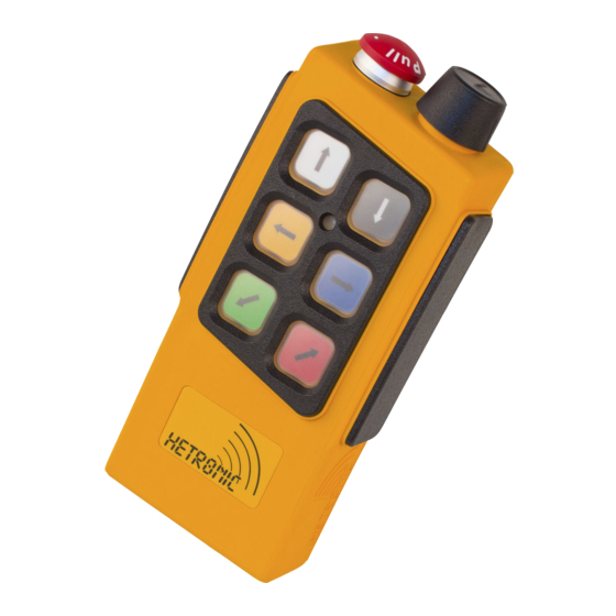
Page 18: Ergo V5
ERGO V5 TRANSMITTER 1. Key Switch and Cap 2. Right Side Bezel and Membrane NOT HALT Emergency Stop 3. Start/Horn Pushbutton 4. Housing 5. Battery (inside) 6. Motion Pushbutton 7. Power LED DK25/17 DK26/17 8. Top Bezel with Membrane DK20 9. -
Page 19: Ergo V8
ERGO V8 TRANSMITTER 1. Key Switch and Cap 2. Right Side Bezel and Membrane NOT HALT 3. Start/Horn Pushbutton Emergency Stop 4. Housing 5. Battery (inside) 6. Motion Pushbutton 7. Latching Option Pushbutton DK25/17 8. Power LED DK26/21 DK20 9. Top Bezel with Membrane 10. -
Page 20: Test Procedures
TEST PROCEDURES • Be sure there are fully charged batteries or optional rechargeable battery pack in the WARNING: FAILURE TO FOLLOW transmitter. INSTRUCTIONS could result in personal • Push in the E-Stop button. injury and/or damage to equipment. Read and •... -
Page 21: Operation
RED to indicate the refer to the Troubleshooting Section. If necessary, diagnostic test in progress.The LED on the contact Hetronic or your Dealer. transmitter flashes GREEN to indicate successful diagnostic testing. WARNING: The Receiver settings are set at 6. -
Page 22: Visual Check
Test the if there is a fault or any problems with the "E-STOP" function as described in the safety check. Contact Hetronic or your dealer crane/machine manufacturer’s operator immediately to repair the system. NEVER manual before beginning any operation. -
Page 23: Maintenance
OPTIONAL BATTERY CHARGING SYSTEM Features • Normal charge or Fast charge of Hetronic standard batteries • Trickle charge - After charging process is complete, battery can remain in charger without being damaged by over-charge. -
Page 24: Fast Charge
Damaged battery cell (open battery inserted cell) If you have questions or problems operating your battery charger, please contact your dealer or Hetronic. Charging the Battery Hetronic Battery Information 1. Insert the battery by placing the end with Standard Hetronic rechargeable batteries are the nickel gold-plated contacts into the battery charger metal hydride type. -
Page 25: Rf Modules
The frequency channel of the transmitter must be set to the frequency channel of the receiver it is going to control. Each Hetronic radio remote control system is pre-set at the factory with the correct frequency channel in the transmitter and receiver. The... -
Page 26: Cs 458 Rf-Synthesizer
& Jumper Settings May 2003 The Hetronic Radio Remote Control System address code and frequency channel are set at the factory. The address code and frequency channel may need to be set if you have purchased a replacement or spare transmitter. -
Page 27: Cs 447 Rf-Synthesizer
& Jumper Settings May 2003 The Hetronic Radio Remote Control System address code and frequency channel are set at the factory. The address code and frequency channel may need to be set if you have purchased a replacement or spare transmitter. -
Page 28: Cs 434 Rf-Synthesizer
& Jumper Settings May 2003 The Hetronic Radio Remote Control System address code and frequency channel are set at the factory. The address code and frequency channel may need to be set if you have purchased a replacement or spare transmitter. -
Page 29: Std-402 Rf-Synthesizer
STD-402 RF-SYNTHESIZER Description of the Transmitter Module The RF unit has a permanently affixed antenna and Description of the Functions receives input power and TTL data by the 3-pin Dubox The frequency range of the STD-402 synthesizer connector (see picture). extends from 429.2500 MHz to 429.7375 Mhz. -
Page 30: Cs 429 Rf-Synthesizer
STD-402 429 MHZ Hetronic CS 429 Frequency & DIP Switch Settings SALS_010.0_CS 429 May 2003 Channel Channel Scan 7, 11, 15, 19, 23, 27, 31, 35, 39, 43 8, 12, 16, 20, 24, 28, 32, 36, 40, 44 9, 13, 17, 21, 25, 29, 33, 37, 41, 45... -
Page 31: Troubleshooting
For help in diagnosing problems in the labels. receiver, refer to the drawing in the "Test the System" • Are there other Hetronic systems at or near the section of this manual that shows the location of each machine site? diagnostic LED. - Page 32 Check wiring on key switch. Replace key not transmit (Power switch, wiring or contact element. LED not flashing) Coder board failure Contact Hetronic or your Dealer. Transmitter is E-Stop switch engaged Pull out the E-Stop pushbutton and press the Start/Horn pushbutton...
- Page 33 External antenna (if used) has loose Tighten antenna and ground connection. connection, poor grounding or Contact Hetronic or your Dealer for more interference information on external antennas. Surge suppressors not installed on Install RC type surge suppressors on all...
-
Page 34: Specifications
48/110/240 VAC 50/60 Hz (+/- 20%) 12/24 VDC (+/- 20%) Up to 18 hours for STD 402 Current <100 mA Safety features Self-monitoring E-Stop circuits ERGO V1 Fail-safe, spring forced E-Stop relay Functions E-Stop pushbutton Self-test during start-up and 6 single-speed pushbuttons operation... - Page 35 BATTERY CHARGER Charging current Normal: 200 mAh Fast charge: 680 mAh Charge time Normal: approx. 6 hours (Standard Hetronic Fast charge: less than 2 hours 1200 mAh battery) (no damage to battery, or negative effect to duty cycles) Temperature range -20°C to +75°C (-4°...
-
Page 36: Installation / Safety Data Sheet
Hetronic assumes no responsibility for the correct operator manuals. installation of the radio remote control system. The equipment operator must ensure that the radio remote control system and the crane/machine operate correctly together. -
Page 37: Definitions & Awg Metric Conversions
DEFINITIONS Acoustic signal A buzzer or other sound intended to be heard as an alert. Analog signal Proportional - stepless or infinite control Belly box A transmitter that is secured to the front of the operator’s body by a belt, strap or breastplate/harness. -
Page 38: Abbreviations
ABBREVIATIONS Analog to digital conversion Analog channel Ampere American Wire Gauge Bits per second Central Processing Unit Digital channel Electromagnetic compatibility Electromagnetic immunity EPROM Electrical programmable read-only memory Frequency modulation Ground High frequency Kilohertz Light emitting diode Lift to operate Milliampere hours Milliampere msec... -
Page 39: Warranty
F.O.B: Hetronic USA, Inc. Oklahoma City, Oklahoma Hetronic, Inc., hereafter referred to as Company, guarantees all items manufactured by it against any defects of material and/or workmanship for a period of one year from the date of shipment. Company makes NO OTHER WARRANTY, EXPRESSED OR IMPLIED, AS TO THE MERCHANTABILITY OR FITNESS OF THE ITEMS FOR THEIR INTENDED USE OR AS TO THEIR PERFORMANCE.
Need help?
Do you have a question about the Ergo V1 and is the answer not in the manual?
Questions and answers