Table of Contents
Advertisement
Quick Links
Advertisement
Table of Contents

Related Manuals for Xantech XTR39

Summary of Contents for Xantech XTR39
- Page 1 XTR39 Hand-Held LCD Remote Control Installation Instructions - 1 -...
- Page 2 ATTENTION: The XTR39 is shipped with the battery disconnected. You must connect the battery. To ensure proper connection between the XTR39 remote and docking cradle, follow the docking procedure. - 2 -...
-
Page 3: Table Of Contents
Box Contents...5 XTR39 Diagram...6 Charging Cradle Diagram ...7 PRELIMINARY SETUP...7 Connecting the Battery Pack ...7 Charging the XTR39 and Charging Cradle LED Indicator...8 SYSTEM SETUP...8 Touch-screen Calibration Adjustment...10 Touch-screen Calibration Test ...10 PROGRAMMING SETUP ...11 XTR39 Dragon™ Installation Guide ...11 INSTALLING AND CONFIGURING THE XTR39 DRAGON™... - Page 4 PLACING COMMANDS ONTO THE GTL’S (CREATING MACRO’S) ...34 Selecting IR Palettes ...35 Associating Commands To GTL’s (Drag And Drop Commands) ...35 Timed Delays ...36 Delete ...36 Testing Commands Placed on the virtual XTR39 Window ...36 TRANSFERRING THE PROJECT...37 Firmware Update...38 Cleaning the XTR39 ...38 Rechargeable Battery Maintenance...38 FCC NOTICE ...39...
-
Page 5: Introduction
Pick it up, and the XTR39 comes to life. Dedicated buttons for the most frequently used buttons such as volume, channel, power, and mute are perfectly positioned. A convenient touch-wheel control sets the XTR39 apart, allowing quick scrolling through menus and commands. -
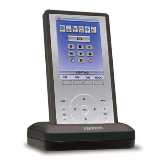
Page 6: Xtr39 Diagram
XTR39 Diagram XTR39 Front View Note: Simulated graphics. - 6 -... -
Page 7: Charging Cradle Diagram
Charging Cradle Diagram Charging Cradle Front View Charging Cradle Rear View PRELIMINARY SETUP Connecting the Battery Pack - 7 -... -
Page 8: Charging The Xtr39 And Charging Cradle Led Indicator
The XTR39 must be charged at least 10 hours straight without being used. Not doing so may harm the life span of the battery. When the XTR39 is placed on the Charging Cradle, the LED indicator will be either ‘red’ or ‘green’. • A ‘red’ LED indicates that the XTR39 battery is charging. - Page 9 Display Settings - Backlight Adjustment Touch and drag the slider to adjust the XTR39 to a desired backlight brightness level. Display Settings - Contrast Adjustment Touch and drag the slider to adjust the XTR39 to a desired contrast level. Display Settings - Backlight Timeout Press “LESS”...
-
Page 10: Touch-Screen Calibration Adjustment
1. From the “XTR39 Setup” page, press the up-arrow to enter calibration adjustment mode. 2. To enter the “XTR39 Setup” page, press and hold the “MUTE” button for 5 seconds. 3. Press anywhere on the touch-screen and a black dot will appear in that exact location. -
Page 11: Programming Setup
XTR39 Dragon™ Installation Guide This guide provides users with step by step instructions on how to install the XTR39 Dragon™ software. Requirements: • 1.0 GHz or greater processor (CPU) • Windows 2000 and Windows XP • 650 MB Hard Drive space (you will need more as your libraries and projects expand) •... - Page 12 2. The installation process will begin: Note: If you do not have the Microsoft .NET (dotnetfx.exe) or InstallShield update on your computer, this will get installed first. 3. Click on the Next button: - 12 -...
- Page 13 4. Enter your name and company and select if the installation should only be available to you or to anyone else who may log into your computer, then click Next: 5. The default installation path for XTR39 Dragon™ is ‘C:\Program Files\Xantech\XTR39 Dragon\’, if this is acceptable click Next. Otherwise click on the Change button and enter the location you wish to install XTR39 Dragon™:...
- Page 14 8. After installation is complete. Click on the Finish button. (Make sure to leave the ‘Yes, check for program update (Recommended) after the setup completes” in order to ensure that you have the latest version of XTR39 Dragon™ installed: - 14 -...
- Page 15 9. After your computer reboots, the installation package will check to make sure that you have the latest version of XTR39 Dragon™ on your computer. 10. You can now run the XTR39 Dragon™ software by double clicking the shortcut on your desktop: Or select XTR39 Dragon™ from your start menu under the Xantech start folder (Start ->...
-
Page 16: Installing And Configuring The Xtr39 Dragon™ Software
USB Connection Open the access cover on the XTR39 and pivot the cover down. Connect the wide end of the included USB cable to the USB port of your PC and the small end to the connector on the lower end of the XTR39 unit (next to the docking cradle connector). -
Page 17: Configuring Usb Port
To configure the USB Port for the first time, complete the following instructions: 1. Connect the XTR39 to the computer via the USB port. Under Windows XP, a Found New Hardware Wizard window asking to connect to Windows Update will appear. Select “No, not this time”... - Page 18 For Windows XP, select the driver found in the “7202XP” folder. For Windows 2000, select the driver found in the “7202w2k” folder. Click “Next”. 4. The XTR39 is now connected to the computer and can be programmed with XTR39 Dragon. Click “Finish” to exit the Found New Hardware Wizard.
-
Page 19: Verifying Pc To Xtr39 Communication
2. There is a communication error between the PC and the XTR39. Please verify the USB cable is properly connected to the unit. When the USB cable is plugged into the PC and the XTR39, the backlight on the XTR39 will stay on (no backlight timeout). -
Page 20: Starting A Project
STARTING A PROJECT With the XTR39 Dragon™ software open and the COM PORT communication verified proceed as follows: From the File menu choose “NEW PROJECT” (CTRL+N) or choose “OPEN PROJECT” (CTRL+O) to modify an existing project file. You may also use the NEW PROJECT or OPEN PROJECT icons located on the Tool Bar at the top of the page. -
Page 21: Creating The Graphical User Interface (Gui)
CREATING THE GRAPHICAL USER INTERFACE (GUI) Through XTR39 Dragon™ software, you can easily create stylish and intuitive screens in multiple pages for controlling any IR Device. Once a project is created and a setup environment chosen, you are automatically placed in Graphics mode and are now ready to create your GUI (Graphical User Interface) screen. -
Page 22: Choosing A Style
Backgrounds To choose a style: 1. Make sure you are in Graphics Mode. If not, click on the Graphics TAB in the XTR39 window. The GRAPHICS window should now be displayed in the work environment. 2. Click on a STYLE from the list in the graphics palette window and browse the associated Source and Function GTL’s shown in the list until a desired style is found. -
Page 23: Placing Function Button Gtl's
Once a Source page has been inserted, you may now start placing Function Buttons (GTL’s) associated with that Source onto the Source Page. 1. Click on the Source button located in the XTR39 window. The Source button should now appear selected. Note: GTL’s have an UP and DOWN graphic associated with them. UP depicts the GTL in its non-selected state and the DOWN graphic depicts the GTL in its Selected state. -
Page 24: Inserting Additional Pages For A Single Source
Component as well as taking the user to the Next Page. For example, a MENU button can be used to call up a menu on the DVD itself and also bring up a page of MENU Cursor buttons on the XTR39 panel for the User to use to navigate through the DVD Menu. -
Page 25: Editing Gtl Properties
Editing GTL Properties Properties of a GTL button can be edited for Text, Font and color. This allows the user to drag a blank GTL button on to the GUI page and edited it to their liking. Each GTL has two states a Down and an Up state. -
Page 26: Creating Labels (Guifx Transports And Icons)
Creating Labels (GuiFX Transports and Icons) GuiFX fonts (www.guifx.com) are automatically installed with XTR39 Dragon. There are two types of fonts, transports and icons. To use a GuiFX symbol, select GuiFX Transports or GuiFX Icons as a font. Enter the repective key (shown on the table below) in the caption text box of the Edit Text / Graphics window. - Page 27 GuiFX Transport Symbols DESCRIPTION Play Stop Pause Fast Forward Rewind Index Forward Index Backward Record Skip Forward Skip Backward ‘ Instant Replay Sound On / Volume Sound Off / Mute ...
-
Page 28: Inserting Labels
XTR39, may be learned into the XTR39 Dragon™ software and stored in Palette files for placement onto the XTR39. In order to do this, the XTR39 must be connected to the PC as outlined above. NOTE: Before starting this section, included in the XTR39 Dragon™ software, is an extensive IR Code Library. -
Page 29: Built-In Ir Code Library
Built-In IR Code Library The XTR39 Dragon™ software has a built-in IR Code Library. This is basically a large database of manufacture’s IR commands for a whole assortment of components at your disposal. If your manufacture’s codes are in our database there might not be any need to ‘teach’ IR commands into the system. -
Page 30: Testing Ir Commands In The Ir Library
Manufacturer/Component, you will need to test the commands to see which Command Group is associated with your specific component. NOTE: To test commands out of the Library, the PC running XTR39 Dragon™ software must be connected to the XTR39 via the USB programming port. -
Page 31: Learning Ir Commands (Xir2)
Learning IR Commands (XIR2) An IR Learning Eye is located on the top end of the XTR39. Note: Commands learned through the XTR39 front learning eye (XIR2 method) are NOT backwards compatible to other Xantech devices (i.e. MRC44/88, URC-2 etc…). - Page 32 Do not press and hold the button until the message goes away. 10. Repeat steps 6 thru 8 for all of the source buttons to be used on the XTR39. Note: Make sure that the IR Learning device is set to “XTR39”.
-
Page 33: Editing Function Names In The Palette Editor
Be sure corresponding source for the commands to be tested is ON and connected to the XTR39. Direct the XTR39 towards the source (IR eye). With the PC still connected to the XTR39’s programming port, select Editor window. The TEST button text will highlight from the drop-down menu. -
Page 34: Creating A Palette File
All of the IR Codes (Palettes or IR Command Groups) should be confirmed and tested before continuing. In the sections to follow, you will be setting up the XTR39 for use in controlling a source. This will consist of setting up the Source Icons, placing IR commands onto the XTR39. -
Page 35: Selecting Ir Palettes
Selecting IR Palettes from the IR Code Library Click on PALETTE EDITOR on the right side XTR39 Dragon™ window if it is not already open. Click on the mode button to change from “Mode: Edit” to “Mode: Palette” Click on the Manufacturer and then the Component Type (i.e. VCR, DVD etc.). -
Page 36: Timed Delays
In XTR39 Dragon, under the menu items, change from Normal Mode to Test Mode. Select the appropriate GTL button in the XTR39 window with the IR codes placed under it to test. (i.e. PLAY button). The button should now appear selected. -
Page 37: Transferring The Project
The project can now be transferred to the XTR39. NOTE: Before continuing, make sure the PC is connected to the XTR39 and a ‘BASE UNIT WHO AM I’ can be performed. To transfer the project to the XTR39, complete the following steps. -
Page 38: Firmware Update
To access the latest firmware updates, proceed to Place the downloaded file in an easy to locate directory. Launch XTR39 Dragon and connect the XTR39 to the computer via the USB port. Go to menu item “Base Unit”. Then select “Upgrade Firmware” and then “XTR39”. -
Page 39: Fcc Notice
FCC NOTICE * Section 15.19 Labeling requirements This device complies with part 15 of the FCC rules. Operation is subject to the following two conditions: (1) This device may not cause harmful interference and (2) This device must accept any interference received, including interference that may cause undesired operation. -
Page 40: Accessory Items
LIMITED WARRANTY Xantech warrants its products to be free of defects in materials or workmanship. This warranty extends for one year from the date of purchase by the consumer. Any products returned freight prepaid to Xantech and found to be defective by Xantech within the warranty period will be repaired or replaced, at Xantech's option, at no charge.
Need help?
Do you have a question about the XTR39 and is the answer not in the manual?
Questions and answers