
Related Manuals for Moxa Technologies MGate 5123 Series


Summary of Contents for Moxa Technologies MGate 5123 Series
- Page 1 MGate 5123 Series Quick Installation Guide Version 1.0, June 2023 Technical Support Contact Information www.moxa.com/support 2023 Moxa Inc. All rights reserved. P/N: 1802051230110 *1802051230110*...
- Page 2 Overview The MGate 5123 is an industrial Ethernet gateway for CANopen/J1939 and PROFINET network communications. Package Checklist Before installing the MGate 5123, verify that the package contains the following items: • 1 MGate 5123 gateway • Quick installation guide (printed) •...
- Page 3 Color Description Single flash: An error counter warning level has been reached. Double flash: A heartbeat event has occurred. No J1939 I/O configured Steady: CAN bus (J1939) communication is Green receiving or transmitting data. Steady: A communication error occurred [as J1939] 1.
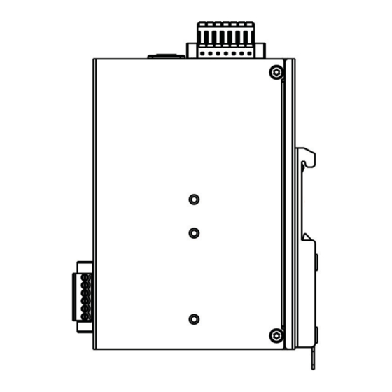
- Page 4 Dimensions DIN Rail Side DIN Rail - 4 -...
- Page 5 Wall Mount Reset Button Restore the MGate to factory default settings by using a pointed object (such as a straightened paper clip) to hold the reset button down until the Ready LED stops blinking (approximately five seconds). Hardware Installation Procedure 1.
- Page 6 The following figure illustrates the two mounting options: Wall- or Cabinet-mounting We provide two metal plates to mount the unit on a wall or inside a cabinet. Attach the plates to the unit’s rear panel with screws. With the plates attached, use screws to mount the unit on the wall.
- Page 7 Ethernet Port (RJ45) Signal Power Input and Relay Output Pinouts Power Power N.O. Common N.C. Power Power Input 2 Input 2 Input 1 Input 1 Specifications Power Parameters Power Input 12 to 48 VDC Power Consumption 455 mA max. Relays Contact Current Rating Resistive load: 2 A @ 30 VDC Environmental Limits...
- Page 8 ATTENTION • This device is an open-type equipment and intended to be installed in a suitable enclosure. • If the equipment is used in a manner not specified by the manufacturer, the protection provided by the equipment may be impaired. •...
Need help?
Do you have a question about the MGate 5123 Series and is the answer not in the manual?
Questions and answers