
Related Manuals for Inelco Dania SSH 9kW


Summary of Contents for Inelco Dania SSH 9kW
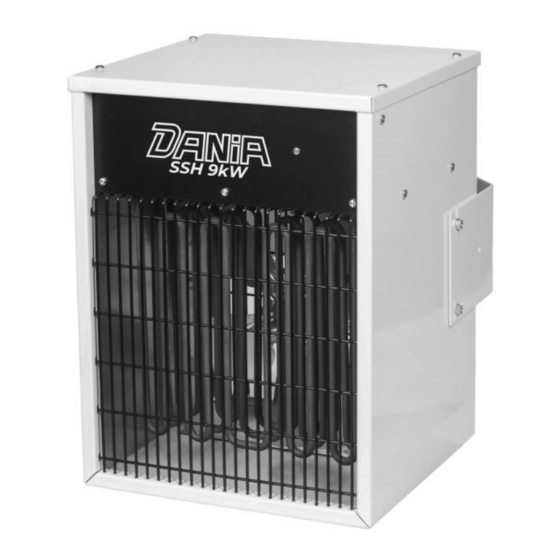
- Page 1 Electric system stationary heater Dania SSH 9kW Instruction manual 02 - 2023 JD...
- Page 2 Electric System Stationary Product 88849447 TYPE 2230 Heater Dania SSH 9kW Important: read the entire user manual before device us- ing, repair or cleaning. Improper use may cause injuries, burns, electric shock or fire. The appliance is not intended for use by persons (including children) with reduced physical, sen-...
- Page 3 Figure 1. Unit elements description. Control LED Heating element Wallmount fixing screw Power cable gland Control cable entry dummy plug Fan with electric motor Wallmount bracket Vertical air flow direction adjustment...
-
Page 4: Mechanical Installation
3 and figure 4. Mechanical installation The DANIA SSH 9kW stationary heater is intended for wall mounting. The appliance must not be placed directly under a wall-outlet. The minimum distances given in figure 2 must be kept. The heaters must not be mounted on the ceiling. - Page 5 Figure 2. Mounting on wall. Minimum distances. In order to ensure to the heater proper working conditions, the mini- mum distances from the ceiling, walls located on the sides of the heater and the minimum installation place height should be main- tained.
- Page 6 Figure 3. Mounting on the wall. Horizontal positions. Pos.2 Pos.1 Pos.3 The wall bracket allows to obtain 3 various horizontal positions in rela- tion to the mounting plane (wall): pos.1 perpendicular to the wall pos.2 tilted to the left pos.3 tilted to the right There are 3 positions of the heated air flow adjustment in the vertical plane available: 1.
- Page 7 Figure 4. Mounting on the wall. Vertical positions A. Vertical position B. Slightly downward direction C. Max downward direction...
-
Page 8: Electrical Installation
Electrical installation The electrical installation should be carried out by a qualified electri- cian in conformity with prevailing regulations. The heaters must be connected to 3x400V~ please refer to the sche- matic figure 5 and figure 6. Power cable should be routed through the power cable gland (figure 1 pos. - Page 9 Figure 6. Wiring diagram for set of 2 up to 6 heaters...
- Page 10 Figure 7. Heater power and steering connectors To gain access to power cables connectors and control devices: con- trol box and thermostat connectors, unscrew the screws securing the cover of the heater housing and then remove the cover. Figure 8. Control box connectors Fig.
-
Page 11: Heater Operation
Figure 9. Thermostat / wired programmer Salus 091FLV2 Inelco recommends SALUS 091FLV2 wired thermostat / programmer to be used with stationary heaters DANIA SSH series. Thermostat manual instruction with wiring diagram is available at: https://salus-controls.eu/ Heater operation First time use While the manufacturing of the heaters, oil residues adhere to the heating elements. -
Page 12: Switching Off
Control Box use Use the control box to set the heating power level (50% or 100%) - please refer to figure 10. The external thermostat will turn on the heat- ing elements when the temperature in the room is below the temper- ature currently set in the thermostat as temperature required. -
Page 13: Maintenance
Overheating If the temperature limiter has been triggered due to overheating, reset as follows: Disconnect the electricity from the heater. Investigate the matter and repair the fault. Reset by opening the lid and pushing the button on top of the temperature limiter (figure 11) until a click sound is heard. -
Page 14: Technical Data
This symbol on Inelco product or its packaging means that the product should not be disposed of with your other household waste.
Need help?
Do you have a question about the Dania SSH 9kW and is the answer not in the manual?
Questions and answers