
Related Manuals for Inelco Dania SSH 3.3kW


Summary of Contents for Inelco Dania SSH 3.3kW
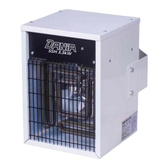
- Page 1 System stationary heater Stacjonarna nagrzewnica elektryczna Dania SSH 3.3kW Instruction manual / Instrukcja obsługi 08 - 2023 JD...
- Page 2 Electric System Stationary Product 88843067 TYPE 2210 Heater Dania SSH 3.3kW Important: read the entire user manual before device us- ing, repair or cleaning. Improper use may cause injuries, burns, electric shock or fire. The appliance is not intended for use by persons (including children) with reduced physical, sen-...
- Page 3 Figure 1. Unit elements description. Control LED Heating element Wallmount fixing screw Power cable Control cable entry dummy plug Fan with electric motor Wallmount bracket Vertical air flow direction adjustment Exhaust grille Air intake...
-
Page 4: Operation
3 and figure 4. Mechanical installation The DANIA SSH 3.3kW stationary heater is intended for wall mounting. The appliance must not be placed directly under a wall-outlet. The minimum distances given in figure 2 must be kept. The heaters must not be mounted on the ceiling. - Page 5 Mount the fan heater on the bracket and adjust the heater to de- sired vertical and horizontal position (refer to figures 3 and 4). Screw the bottom bolt in and tighten all bolts. Use wall fasteners appropriate for the wall material and weight of the unit with a reasonable safety margin.
- Page 6 Figure 3. Mounting on the wall. Horizontal positions. Pos.2 Pos.1 Pos.3 The wall bracket allows to obtain 3 various horizontal positions in rela- tion to the mounting plane (wall): pos.1 perpendicular to the wall pos.2 tilted to the left pos.3 tilted to the right There are 3 positions of the heated air flow adjustment in the vertical plane available: 1.
- Page 7 Figure 4. Mounting on the wall. Vertical positions A. Horizontal position B. Slightly downward direction C. Max downward direction...
-
Page 8: Electrical Installation
Electrical installation The electrical installation should be carried out by a qualified electri- cian in conformity with prevailing regulations. The heaters must be connected to 230V please refer to the schematic figure 5 and figure 6. Connection between the Control Box and DANIA SSH stationary heat- er, should be made with a cable 0,75mm (or similar may be used). - Page 9 Figure 6. Wiring diagram for set of 2 up to 6 heaters...
- Page 10 Figure 7. Heater power and steering connectors To gain access to power cables connectors and control devices: con- trol box and thermostat connectors, unscrew the screws securing the cover of the heater housing and then remove the cover. Figure 8. Control box connectors Fig.
-
Page 11: Heater Operation
Figure 9. Thermostat / wired programmer Salus 091FLV2 Inelco recommends SALUS 091FLV2 wired thermostat / programmer to be used with stationary heaters Dania SSH series. Thermostat manual instruction with wiring diagram is available at: https://salus-controls.eu/ Important: use only thermostats with NO/COM voltage-free relay on output. -
Page 12: Switching Off
Control Box use Use the control box to set the heating power level (50% or 100%) - please refer to figure 10. The external thermostat will turn on the heat- ing elements when the temperature in the room is below the temper- ature currently set in the thermostat as temperature required. -
Page 13: Maintenance
This symbol on Inelco product or its packaging means that the product should not be disposed of with your other household waste. -
Page 15: Technical Data
Technical data: Mains voltage [V]: 230V 50Hz Max mains current [A]: 14.3A Fan diameter [mm]: Air flow [m Product size [mm] 410x300x260 Heating power [kW]: 1,65kW/3.3kW Protection class IP IP44 All trademarks, logos and brand names are the property of their re- spective owners. - Page 16 Systemowa nagrzewnica Produkt 88843067 TYP 2210 stacjonarna Dania SSH 3.3kW Ważne: przed użyciem, naprawą lub czyszczeniem urzą- dzenia przeczytaj instrukcję obsługi w całości. Niewłaściwe użytkowanie może spowodować obrażenia, oparzenia, porażenie prądem lub pożar. Urządzenie nie jest prze- znaczone do użytku przez osoby (w tym dzieci) o ograniczonych możliwościach fizycznych, sensorycznych lub umysłowych, a także...
- Page 17 Rysunek 1. Opis elementów urządzenia. Dioda kontrolna LED Element grzejny Śruba mocująca uchwyt Kabel zasilający Zaślepka otworu na kabel urządzenia sterującego Wentylator z silnikiem Uchwyt do mocowania naściennego Regulacja pochylenia w pionie Kratka wylotowa Kratka wlotowa...
- Page 18 Aby uzyskać szczegółowe informacje, patrz odpowiednio rysunek 5 lub rysunek 6. Inelco zaleca użycie termostatu Salus 091FLV2 z programatorem do sterowania nagrzewnicami stacjonarnymi DANIA SSH. Więcej szcze- gółów można znaleźć na rysunku 9. Ważne: aby pracować nagrzewnica musi być połączona z Control Box oraz z zewnętrznym termostatem.
-
Page 19: Instalacja Mechaniczna
Nagrzewnica montowana jest na ścianie za pomocą uchwytu ścienne- go, który umożliwia uzyskanie 3 różnych pozycji w pionie i 3 różnych pozycji w poziomie – patrz rysunek 3 i rysunek 4. Instalacja mechaniczna Nagrzewnice stacjonarne DANIA SSH 3,3kW przeznaczone są do mon- tażu naściennego. - Page 20 Rysunek 2. Montaż na ścianie. Minimalne odległości. Aby zapewnić nagrzewnicy odpowiednie warunki pracy należy za- chować minimalne odległości od sufitu, ścian pomieszczenia znajdu- jących się po bokach oraz minimalną wysokość miejsca montażu. Właściwe umiejscowienie nagrzewnicy zapewni efektywne i równo- mierne ogrzewanie pomieszczenia, bezpieczeństwo użytkowania oraz zabezpieczy przechodzące osoby przed możliwością...
- Page 21 Rysunek 3. Montaż na ścianie. Ustawienia poziome. Pozycja 2 Pozycja 1 Pozycja 3 Uchwyt ścienny pozwala na uzyska- nie 3 pozycji w płaszczyźnie pozio- mej (widok z góry): poz.1 prostopadła do ściany poz.2 odchylona w lewo poz.3 odchylona w prawo Dostępne są...
- Page 22 Rysunek 4. Montaż na ścianie. Ustawienia pionowe. A. Ustawienie poziome B. Odchylenie lekko w dół C. Maksymalne odchylenie w dół...
- Page 23 Instalację elektryczną powinien wykonać wykwalifikowany elektryk, zgodnie z obowiązującymi przepisami. Nagrzewnice należy podłączyć do sieci 230V, patrz schemat rysunek 5 i rysunek 6. Połączenie pomiędzy Control Box a nagrzewnicą stacjonarną DANIA SSH należy wykonać przewodem o przekroju 0,75mm2 (można zasto- sować...
- Page 24 Rysunek 6. Schemat podłączenia zestawu od 2 do 6 na- grzewnic...
- Page 25 Rysunek 7. Złącza zasilania i sterowania nagrzewnicy Aby uzyskać dostęp do złączy kabli zasilających i urządzeń sterują- cych: Control Box i złączy termostatu należy odkręcić śruby mocują- ce pokrywę obudowy nagrzewnicy, a następnie zdjąć pokrywę. Rysunek 8. Złącza Control Box Rys.
- Page 26 Rysunek 9. Termostat / programator przewodowy Salus 091FLV2 Inelco rekomenduje przewodowy termostat/programator SALUS 091FLV2 do stosowania z nagrzewnicami stacjonarnymi serii Dania SSH. Instrukcja obsługi termostatu wraz ze schematem połączeń jest dostępna pod adresem: https://salus-controls.eu Ważne: należy stosować wyłącznie termostaty z beznapięcio- wym przekaźnikiem NO/COM na wyjściu.
- Page 27 Użycie Control Box Za pomocą Control Box ustaw poziom mocy grzania (50% lub 100%) - patrz rysunek 10. Termostat zewnętrzny włączy elementy grzejne, gdy temperatura w pomieszczeniu spadnie poniżej temperatury aktualnie ustawionej na termostacie. Dioda kontrolna (rysunek 1, poz. 1) świeci się.
- Page 28 Ten symbol na produkcie Inelco lub jego opakowaniu oznacza, że produktu nie należy wyrzucać wraz z innymi odpadami do- mowymi. Twoim obowiązkiem jest utylizacja zużytego sprzętu oddzielnie od odpadów komunalnych.
-
Page 29: Dane Techniczne
Dane techniczne: Napięcie zasilania [V]: 230V 50Hz Max pobór pradu [A]: 14.3A Średnica wentylatora [mm]: Przepływ powietrza [m Wymiary produktu [mm] 410x300x260 Moc grzewcza [kW]: 1,65kW/3.3kW Klasa ochronności IP IP44 Wszystkie znaki towarowe, logo i nazwy marek są własnością ich odpo- wiednich właścicieli. - Page 31 Notes / notatki...
Need help?
Do you have a question about the Dania SSH 3.3kW and is the answer not in the manual?
Questions and answers